


Installation Drawings
66
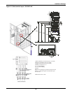
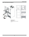
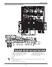
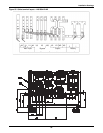
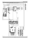
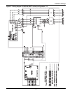
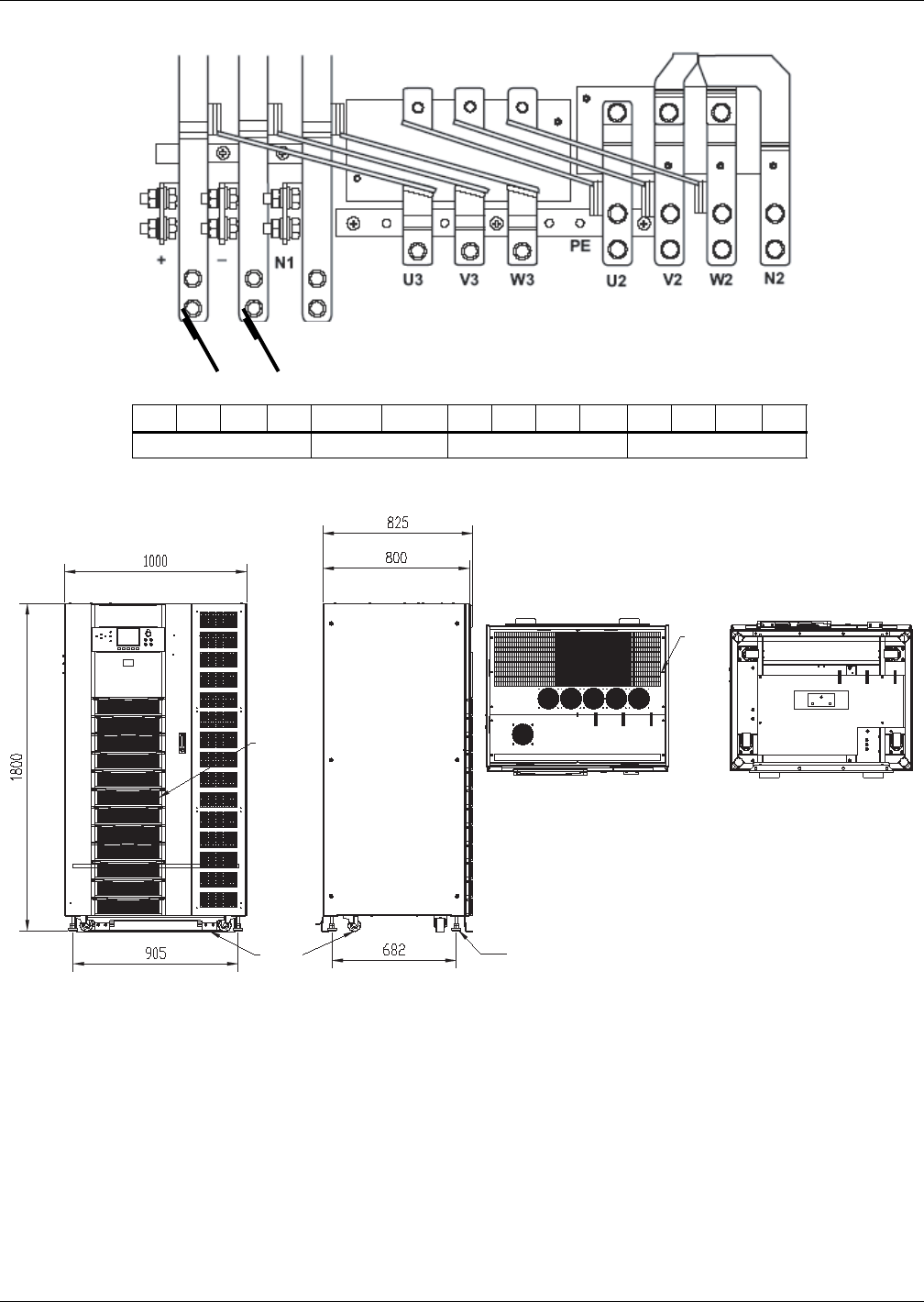
Figure 52 Cable terminal layout—100-120kVA NX
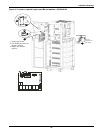
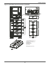
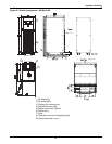
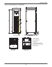
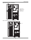
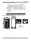
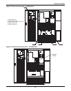
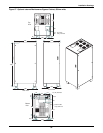
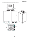
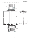
Figure 53 General arrangement—140-200kVA NX
U1 V1 W1
U1V1W1N1Batt +Batt -N1U3V3W3U2V2W2N2
Input Batt Bypass Output
1. Air inlet grille
2. Air outlet grille
3. Casters
4. Adjustable fixing feet
5. Seismic anchors (optional)
6. Cable entry
1
2
4
5
3