Dimensional Drawings
38
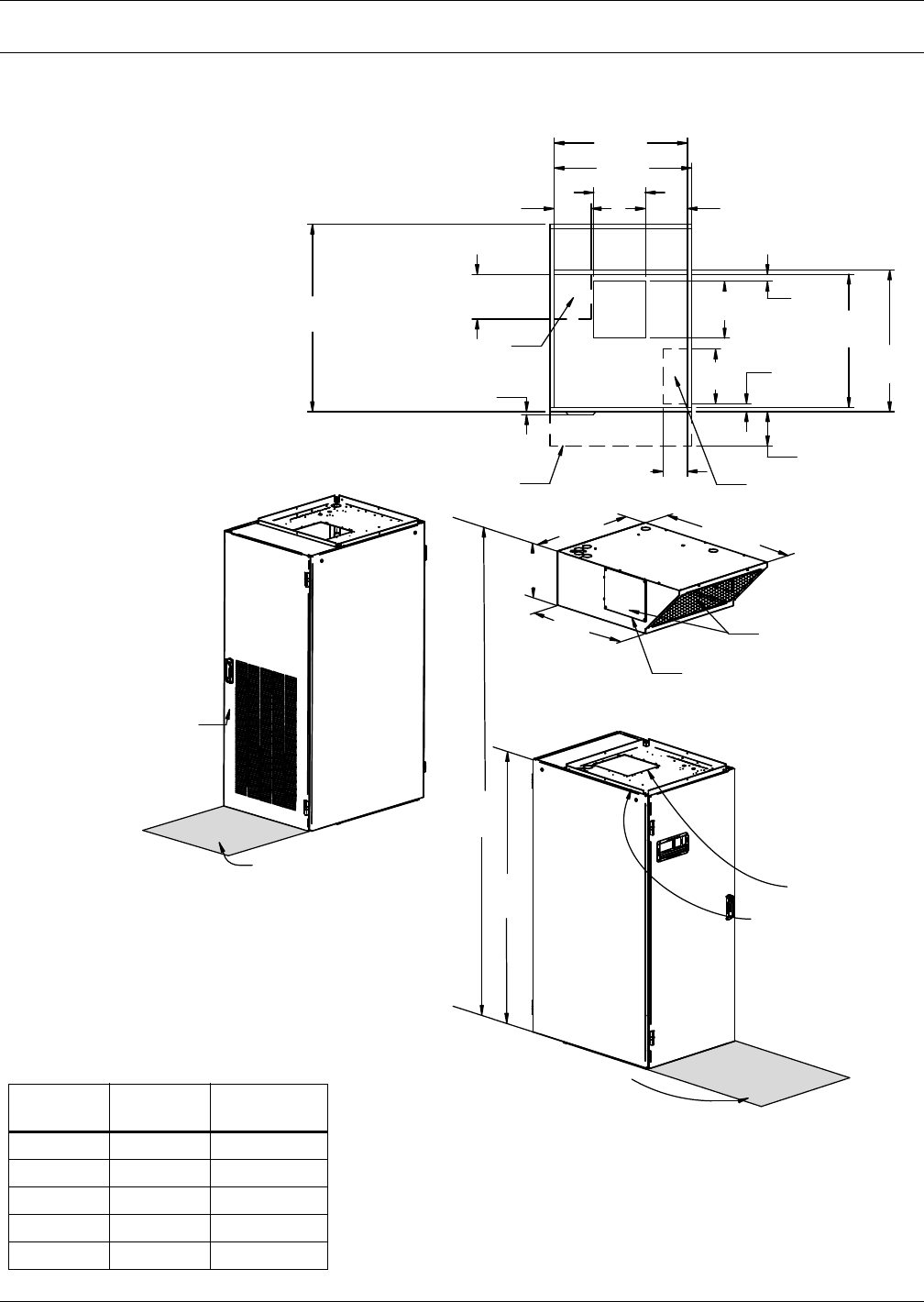
14.0 DIMENSIONAL DRAWINGS
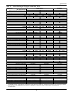
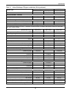
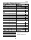
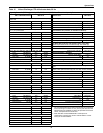
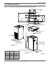
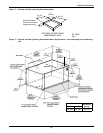
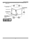
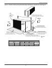
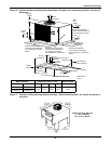
Figure 11 Cabinet and floor planning dimensional data—Horizontal flow models
DPN001523
Pg. 2, Rev. 1
Filter Access
by Opening Door
UNIT
TOP VIEW
32-1/2"
(826mm)
5/8"
(16mm)
9-5/8"
(244mm)
8-1/2"
(216mm)
31-1/2"
(800mm)
1-7/8"
(48mm)
12-1/2"
(318mm)
30-1/2"
(775mm)
30-1/2"
(775mm)
32-1/2"
(826mm)
32-1/2"
(826mm)
1-5/8"
(41mm)
13"
(330mm)
Projection of
Display Bezel
Standard Piping Location
45-1/8"
(1147mm)
5-1/2"
(140mm)
15-1/16"
(382mm)
76"
(1930mm)
91-1/16"
(2313mm)
Blower Outlet with
1" (25.4mm) Flange
Shaded area indicates
a recommended
clearance of 34" (864mm)
for component access
Shaded area indicates a recommended
clearance of 34" (864mm) for component access
UNIT DIMENSIONAL DATA
FRONT VIEW
UNIT DIMENSIONAL DATA
REAR VIEW
10-1/4"
(260mm)
7/8" (22.2mm) Flange for
Duct or Plenum Connection
43-5/16"
(1100mm)
11-3/4"
(298mm)
Remove Blocker Panel
for Air Discharge Left
and/or Right Side Panels
Standard Electrical Outlet
Location Through Unit
12-5/8"
(321mm)
Discharge Air Opening
Plenum Overhang
UNIT TOP VIEW
50 Hz
Models
60 Hz
Models
Unit Weight
lb. (kg)
BR059E BR060E 649 (294)
BR065A BR067A 744 (337)
BR070WG BR071WG 814 (369)
BR101C BR102C 659 (299)
BM058G BM061G 854 (387)


