


Installing and Removing a Power Supply
Enterasys G-Series Hardware Installation Guide 2-5
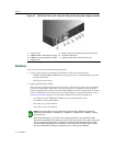
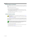
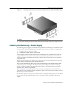
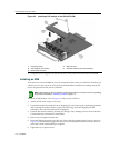
Figure 2-1 Attaching the Brackets to the Switch (G3G124-24 with G3G-24TX IOM shown)
4. Usingyourmountinghardware,attachthefrontofthebracketstotherack.Tightensecurely.
Installing and Removing a Power Supply
ThefollowingpowersuppliesareavailabletobepurchasedfromEnterasysforinstallationonthe
G‐Seriesswitch.Followtheappropriateinstructionsinthissectiontoinstallyourcomponent(s):
•G3‐PWR,a400‐wattACpowersupply
•G3‐PWR‐POE,a1200‐wattACpowersupply
Powersuppliescanbemixedand
canbeusedasredundantornon‐redundant.Theswitchwill
supportafull15.4wattsofpowerto96portsinnon‐redundantpowermode,and9.4wattsof
powerto96portsinredundantpowermode.Bydefault,theG‐Seriesswitchissettooperatein
redundantmode.
Whentwopowersuppliesareinstalled,thepowerfromeachisevenlydistributed.Ifonepower
supplyfails,thesecondpowersupplyassumestheload.
TheG3switchautomaticallyallotspowertothebaseboardandtoeachinstalledmodule.Each
component’spowerconsumptionissubtractedfromtheavailablepowerand
theremaining
powerisequallydistributedamonginstalledPoEmodules.APoEmodulemustbeallotteda
minimumof37wattstobeoperational.
RefertoAppendix AforpowerspecificationsofvariousG3components.For informationon
usingtheCLItosetthestatusofpowerredundancyandtoreview
systempowersettings,referto
theEnterasysG‐SeriesCLIReference.
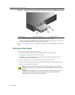
BeawarethatwhenyoureceiveyourG‐Seriesswitch,acoverplatewillbeinplaceoverthePWR2
powersupplyslot,leavingPWR1openforyourconveniencewheninstallingthefirstpower
supply.
1 Screws 2 Rack-mount brackets