


Connecting to the Network
2-14 Installation
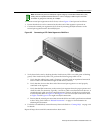
5. WhenyouarereadytobeginconfiguringtheG‐SeriesEthernetswitch,usetheproceduresin
“CompletingtheInstallation”onpage 2‐20topowerontheswitchandbootthesoftware.You
willperforminitialsetupbyenteringCLIcommandsonthe managementconsole.
Foradescriptionofhowto
usetheCLIanddescriptionsofalltheCLIcommands,refertothe
EnterasysG‐SeriesCLIReference.
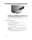
Connecting to the USB Console Port
InadditiontoitsRJ45consoleport,theG‐Seriesswitchalsosupportsconsoleoperationthrougha
USBconsoleport.Toconnect,youwillneedthefollowinguser‐suppliedcomponents:
•USBTypeAtoMini‐USBcable
•Thirdpartydevicedriverdownloadedfrom:
http://www.silabs.com/tgwWebApp/public/web_content/products/Microcontrollers/USB/en/
mcu_vcp.htm
Connecting to the Network
ThefollowingprocedurescoverthecableconnectionsfromthenetworkorotherdevicestotheG‐
SeriesEthernetswitchIOMportsanduplinkports.
• ConnectingUTPCablestoRJ45Portsonpage 2‐14
• InstallingOptionalSFP/XFPonpage 2‐17
• ConnectingFiber‐OpticCablestoSFP/XFPPortsonpage 2‐19
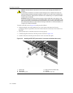
Connecting UTP Cables to RJ45 Ports
RJ4510000BASE‐TXfrontpanelportsontheG3G124‐24andG3G124‐24PbaseunitsandG3G‐
24TXIOMsupportAutoMDIX,whichmeansthatyoucanusestraight‐throughorcrossover
twistedpaircabling.
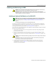
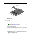
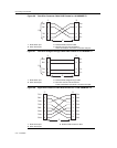
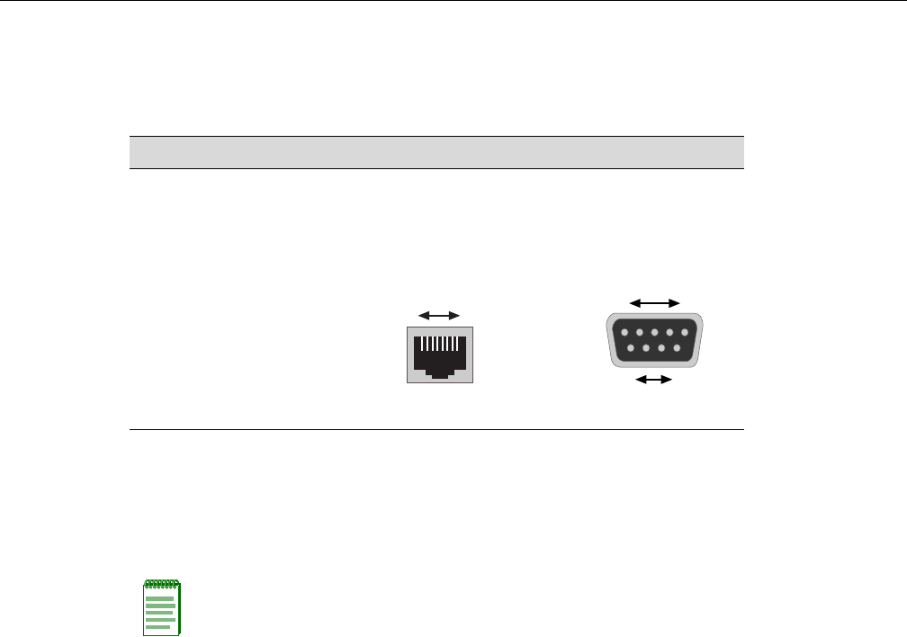
Table 2-3 RJ45 to DB9 Adapter Pinout
Signal RJ45 Pin DB9 Pin
Receive (RX) 1 2
Transmit (TX) 4 3
Ground (GRD) 5 5
RJ45 Connector (Female)
81
Pins
DB9 Connector (Female)
Pins
15
69
Note: Before connecting a PC into the G-Series USB console port, you must download to the PC
and install a third party driver located at
http://www.silabs.com/tgwWebApp/public/web_content/products/Microcontrollers/USB/en/
mcu_vcp.htm.