


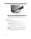

Installing and Removing a Power Supply
2-8 Installation
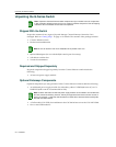
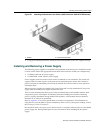
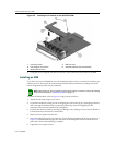
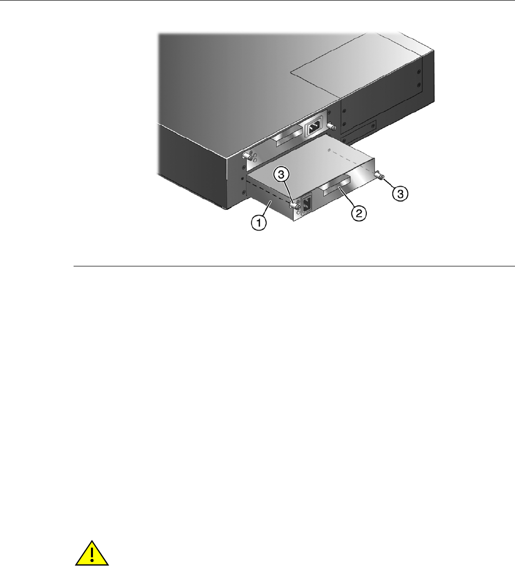
Figure 2-2 Installing a Power Supply Module (1200-watt module into PWR 2 slot shown)
7. Securethepowersupplytothechassisbytight eningthecaptivescrews.
8. Ifyouareinstallinganadditionalpowersupply,repeatstep4throughstep7.Ifnot, ensure
thattheunusedpowerslothasacoverplateinstalledoverit.
Referto“PowerSupplyPlanning”onpage 2‐6for
informationonconfiguringtheswitch’spower
mode.
Removing a Power Supply
Toremoveapowersupply,proceedasfollows:
1. Attachananti‐staticwriststrapbeforehandlingthepowersupplymodule.
2. Unplugtheassociatedpowercordfromtheoutlet.
3. UnplugthepowercordfromtheACinlet(associatedwiththepowersupplyyouare
removing)atthebackofthechassis.
4. Unscrewthe
captivescrewstoreleasethepowersupplyfromthechassis.
5. Removethepowersupplybygraspingthehandleandpullingitstraightoutofthechassis.
6. Fastenacoverplateovertheemptyslot.
1 Power supply 2 Power supply handle 3 Captive screws
Caution: If you plan to operate the chassis with only one power supply, be sure to install the
coverplate in place of the removed power supply to contain EMI radiation and ensure proper air
circulation.
Precaución: Si desea trabajar sólo con una fuente de poder, no olvide colocar la tapa en el
compartimiento de la fuente de poder que haya eliminado, para reducir la interferencia
electromagnética y para asegurar una buena ventilación.