


Connecting to the Network
Enterasys G-Series Hardware Installation Guide 2-15
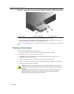
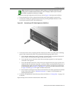
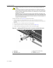
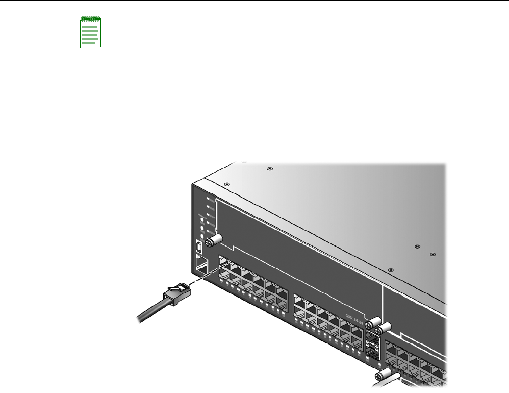
ToconnecttwistedpairsegmentstotheG‐Series,refertoFigure 2‐5and proceedasfollows:
1. Ensurethatthedevicetobeconnectedattheotherendofthesegmentispoweredon.
2. ConnectthetwistedpairsegmenttotheG‐SeriesbyinsertingtheRJ45connectoronthe
twistedpair
segmentintothedesiredRJ45port.
Figure 2-5 Connecting a UTP Cable Segment to RJ45 Port
3. VerifythatalinkexistsbycheckingthattheLink/ActivityLEDison(solidgreenorblinking
green).IftheLink/ActivityLEDisoff,performthefollowingstepsuntilitison:
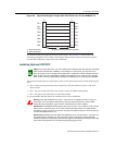
a. VerifythatthecablingbeingusedisCategory 5orbetterwithan
impedancebetween85
and111 ohmswithamaximumlengthof100meters(328feet).
b. Verifythatthedeviceattheotherendofthetwistedpairsegmentisonandproperly
connectedtothesegment.
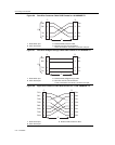
c. VerifythattheRJ45connectorsonthetwistedpairsegmenthavetheproperpinoutsand
check
thecableforcontinuity.Typically ,acrossovercableisusedbetweenhubdevices.A
straight‐throughcableisusedtoconnectbetweenG‐Seriesesorhubdevicesandanend
user(computer).RefertoFigure 2‐6andFigure 2‐7forfour‐wireRJ45connections.Refer
toFigure 2‐8andFigure 2‐9
foreight‐wireRJ45connections.
d. EnsurethatthetwistedpairconnectionmeetsthedBlossandcablespecificationsoutlined
intheCablingGuide.Referto“RelatedDocuments”onpage xviforinformationon
obtainingthisdocument.
4. Ifalinkisnotestablished,contactEnterasys Networks.Referto“GettingHelp”onpage xviii
fordetails.
Repeatallstepsaboveuntilallconnectionshavebeenmade.
Note: All RJ45 front panel and IOM ports support Category 5 Unshielded Twisted Pair (UTP)
cabling with an impedance between 85 and 111 ohms. Category 3 cable may be used if the
connection is going to be used only for 10 Mbps.