


Checking the LEDs
3-2 Troubleshooting
Checking the LEDs
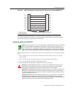
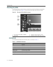
ThefollowingsectionsdefinethebehavioroftheLEDsontheG‐SeriesEthernetswitchchassis
andontheIOMs.RefertoFigure 3 ‐1forthelocationoftheLEDsonthechassisandIOMs.
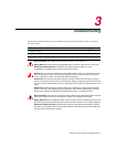
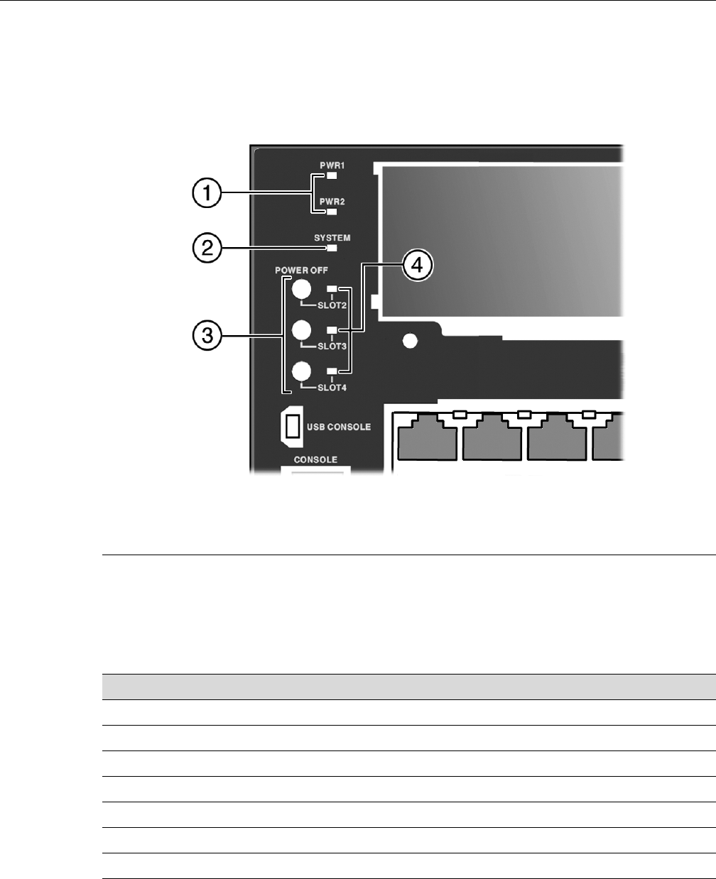
Figure 3-1 G3 system LEDs (G3G124-24 shown)
SYSTEM LED
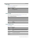
TheSYSTEMLEDindicatesthestateofthesystem,asdescribedinTable 3‐1.
1 Power Supply LEDs (PWR1 and PWR2) 3 IOM power off buttons (Slot 2, 3 and 4)
2 System LED 4 IOM power off status LEDs (Slot 2, 3 and 4)
Table 3-1 SYSTEM LED Definitions
Display Status
Off No power.
Solid red Major system failure, including failure to boot.
Blinking red Power on self-test failed.
Solid amber Diagnostics are running.
Blinking amber Functional image is loaded.
Blinking green System is booting.
Solid green System is fully operational.