


EPSON Perfection 610 Revision B
Troubleshooting Troubleshooting 23
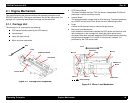
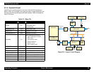
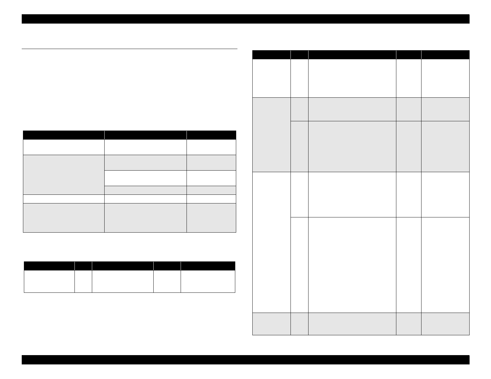
3.3 Troubleshooting
This section describes how to troubleshoot problems according to
exhibited phenomenons.
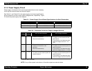
See Table 3-2 that enables you to find the defective part to the unit
level. Then refer to the corresponding table for checkpoints and
solutions.
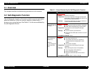
Table 3-2. Problems and Corresponding Tables to Refer to
Phenomenon Problem Refer to:
The scanner is turned on but
does not operate.
The scanner is not initialized. Table 3-3
“Fatal Error” occurs. The
scanner is turned off and back
on but still shows the same
error.
The carriage unit does not
operate.
Table 3-4
The carriage unit operates but
the error is indicated.
Table 3-5
The lamp does not light up. Table 3-6
Image is not read clearly. Image is not read clearly. Table 3-7
“Communication Error” occurs.
Communication with the host
is attempted again, but the
same error occurs.
USB interface error Table 3-8
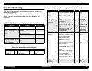
Table 3-3. The scanner is not Initialized.
Cause Step Checkpoints Finding Remedy
CN1 on the power
supply board is
disconnected.
1
Is CN1 on the power
supply board
disconnected?
Yes
Connect CN1 to the
power supply
board.
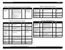
Table 3-4. The carriage unit does not operate.
Cause Step Checkpoints Finding Remedy
The PS
(Power
Supply)
board is
defective.
1 With scanner power on, check
CN101 for the output voltage at
the pins below.
• Pins: 8/9 (+) and 6/7 (-)
• Voltage: +24VDC
No Replace the PS
board.
The carriage
drive
mechanism
is defective.
2
Is grease (G-26) properly
applied?
(See Chapter 6.)
No Apply grease to
the specified
points properly.
3 • With the upper housing
removed, turn the scanner on,
and check that the CR motor is
live.
• Remove the CR motor, and
check that the carriage unit
moves smoothly.
No Check the
carriage unit, and
replace any
defective part or
disassemble and
assemble the
scanner again.
The CR
motor is
defective.
4 Disconnect CN6 on the main
board. Then, using a tester,
check that the coil resistance at
each point below is 6.2
Ω
.
1. Between Pins 2 and 4
2. Between Pins 1 and 3
No Replace the CR
motor and go to
step 4.
5 Follow the steps below to check
for the CR motor driver circuit.
1. Set the meter to
Ω
.
2. Place the (-) terminal of the
tester on Pins 1, 2, 3, and then
4 of the CN6 on the main
board.
3. Place the (+) terminal of the
tester on Pin 6 or 7 of the CN4
on the main board.
4. Turn the scanner off, and
check that the meter shows
“
∞
“for each pin.
No Replace the main
board.
The main
board is
defective.
6 --- --- Replace the main
board.