


EPSON Perfection 610 Revision B
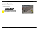
Assembly and Disassembly Disassembly Procedures 31
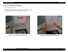
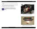
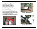
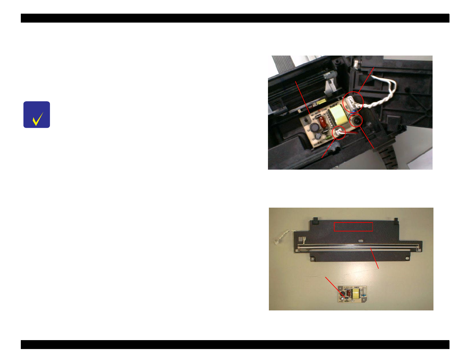
6. Disconnect the connector for the Inverter Lamp from the Inverter
Board.
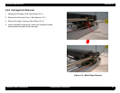
7. Remove the black screw and disconnect the 2-pin connector for the
CCD sensor, and then remove the Inverter Board.
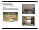
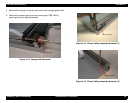
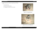
8. Remove the Inverter Lamp from the carriage cover.
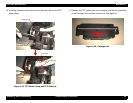
Figure 4-10. Inverter Board Removal
Figure 4-11. Inverter Lamp Removal
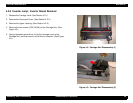
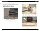
CHECK
POINT
When installing the Inverter Lamp, locate the
connectors correctly as shown in the following
figures.
Black Screw
Connector (2-pin)
Connector
Inverter Board
Carriage Cover
Inverter Lamp
Connector (2-pin)