


EPSON Perfection 610 Revision B
Assembly and Disassembly Disassembly Procedures 39
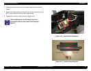
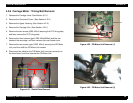
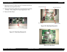
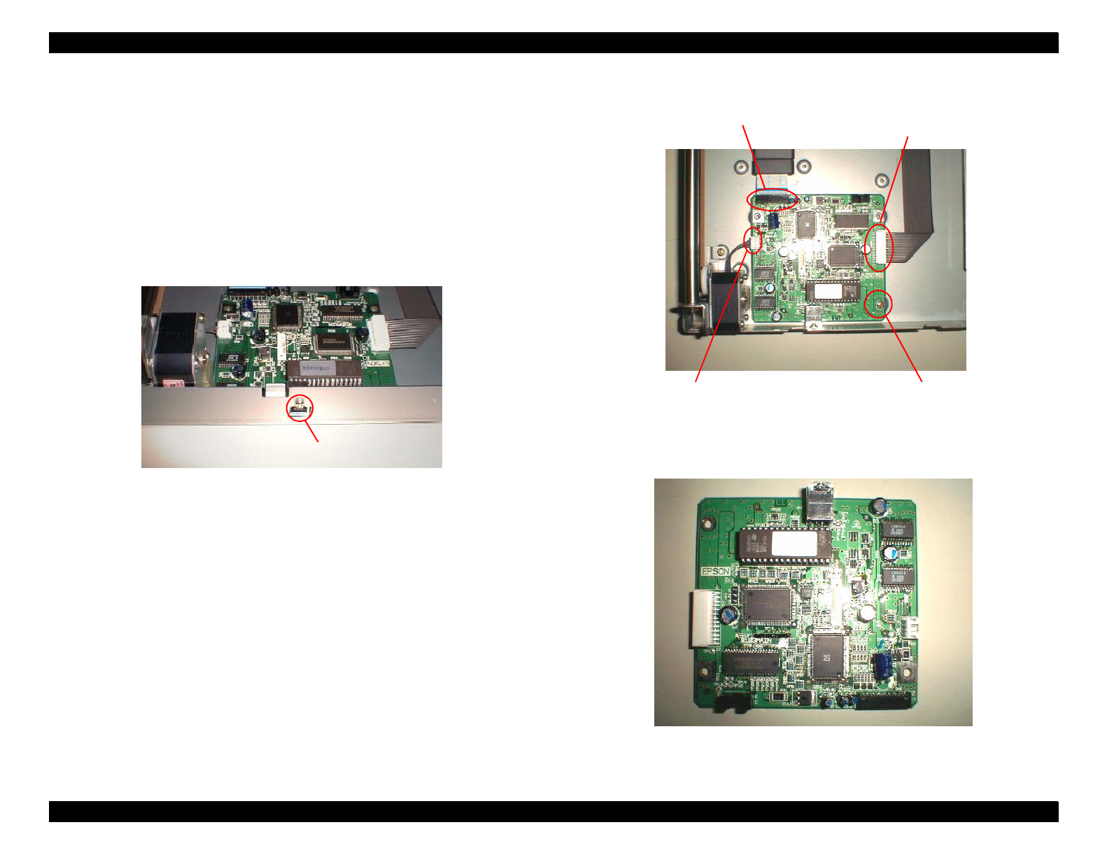
7. Remove the screw (CP, M3x5) near the I/F connector and the one
(CBS, M3x5) securing the Main Board.
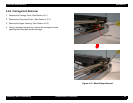
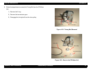
8. Disconnect the following cables from the corresponding connectors;
CR Motor - CN6, carriage FFC, Power Supply Board - CN4.
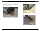
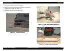
9. Remove the Main Board.
Figure 4-27. Main Board Removal (2)
Figure 4-28. Main Board Removal (3)
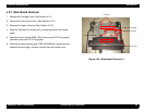
Figure 4-29. Main Board
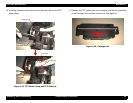
CP Screw (M3x5)
CBS Screw (M3x5)
CN6 (CR Motor)
CN4 (Power Supply Unit)
Carriage FFC Connector