


EPSON Perfection 610 Revision B
Assembly and Disassembly Disassembly Procedures 36
4.2.6 Carriage Motor / Timing Belt Removal
1. Release the Carriage Lock. (See Section 4.2.1.)
2. Remove the Document Cover. (See Section 4.2.2.)
3. Remove the Upper Housing. (See Section 4.2.3.)
4. Remove the Carriage Unit. (See Section 4.2.5.)
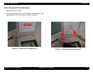
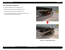
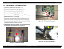
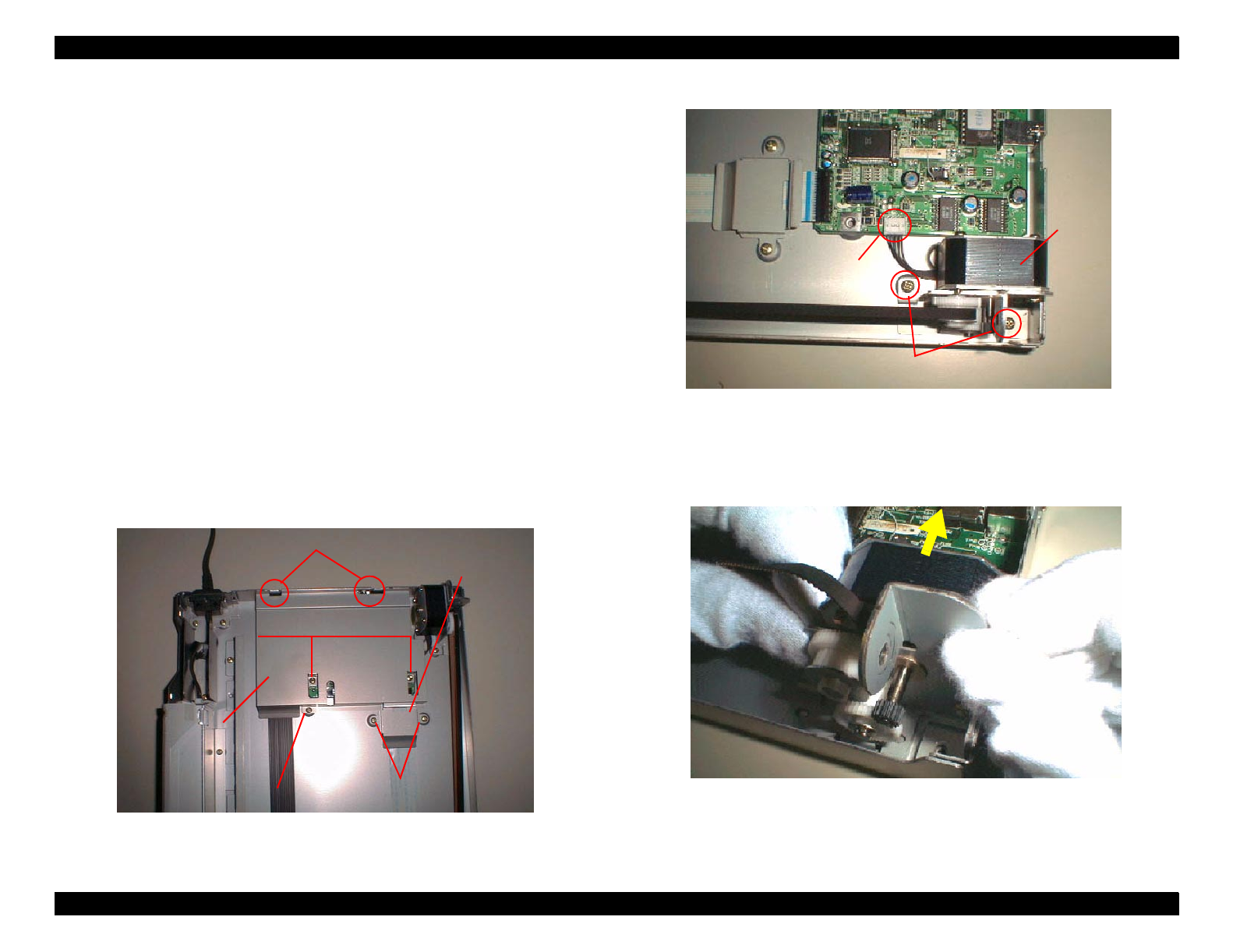
5. Remove the two screws (CBS, M3x4) securing the FFC fixing plate,
and then remove the FFC fixing plate.
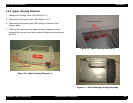
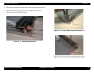
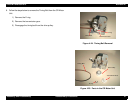
6. Remove the three screws (gold, CBS, M3x4/M3x6) and the two
hooks at the rear edge, and then remove the main board cover.
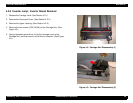
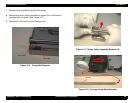
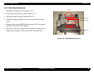
7. Remove the two screws (gold, CBS, M3x4) securing the CR Motor
Unit, and then shift the CR Motor Unit inward.
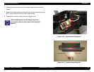
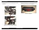
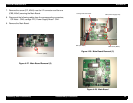
8. Disconnect the cable for the CR Motor Unit from the connector on
the main board, and then remove the CR Motor Unit.
Figure 4-21. Shield Plate Removal
Figure 4-22. CR Motor Unit Removal (1)
Figure 4-23. CR Motor Unit Removal (2)
6. Hooks
6. CBS Screw (M3x4)
5. CBS Screws (M3x4)
6. CBS Screws M3x6)
5. FFC Fixing Plate
6. Main Board Cover
CR Motor Unit
Connector
CBS Screws (M3x4)