


EPSON Perfection 610 Rev. B
Appendix Overview 48
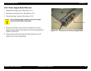
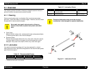
7.1 Overview
This section provides useful information for servicing this scanner.
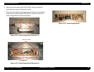
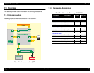
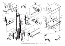
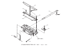
7.1.1 Interconnection
Following figures shows interconnection of the scanner.
Figure 7-1. Interconnection (USB)
7.1.2 Connector Assignment
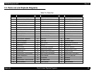
Table 7-1. Connector Summary- B103MAIN
Lam p
Inverter B oard
B071 ISN
B o a rd
CN1
CN2
B103PNL
AC Plug
CR
Motor
CN1
CN2
CN1
B103MAIN Board
CN5
CN6
CN7
(2 -pi n)
(2 -pi n)
(2 -pi n)
(5 -pi n)
(18-pin) (4-pin)
(12-pin)
Power Supply Board
USB
CN1
(4 -pin )
CN4
CN101
CN102
Connector
Number
Description
Number
of Pins
Refer to:
B103MAIN Board
CN4 To the Power Supply Board 12 Table 7-2
CN5 To the CCD Sensor Board 18 Table 7-3
CN6 To the CR Motor 4 Table 7-4
CN7 To the USB Cable 4 Table 1-1
Power Supply Board
CN1 AC Input 2 Table 7-5
CN101 To the Control Board 12 Table 7-2
CN102 To the Panel Board 5 Table 7-6
CCD Sensor Board
CN1 To the Control Board 18 Table 7-3
CN2 To the Inverter Board 2 Table 7-7
Inverter Board
CN1 To the CCD Sensor Board 2 Table 7-7
CN2 To the Lamp 4 Table 7-8