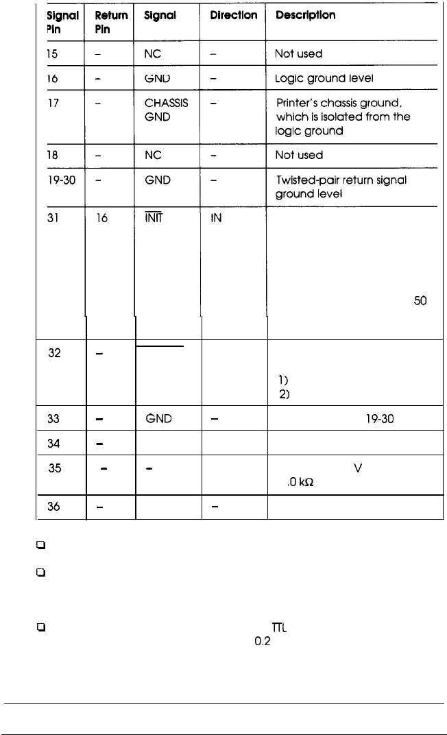
When this level becomes
LOW, the printer controller is
reset to its power-on state
and the print buffer is
cleared This level is
normally HIGH: its pulse
width must be more than
50
microseconds at the
receiving terminal.
32
-
ERROR
OUT This level becomes LOW
when the printer is:
1)
out of paper
2)
in an error state
33
-
GND
-
34
-
NC
35
-
-
OUT
Same as for pins
19-30
Not used
Pulled up to 5 V through
1
.O
kR
resistance
36
-
Note:
NC
-
Not used
P
The column heading “Direction” refers to the direction of signal flow as
viewed from the printer.
0
“Return” denotes the twisted-pair return, to be connected at signal
ground level. For the interface wiring, be sure to use a twisted-pair
cable for each signal and to complete the connection on the return
side.
P
All interface conditions are based on the TTL level. Both the rise and fall
times of each signal must be less than
0.2
microseconds,
Appendix A-9


