


Appendix A System Interface Description
A-7
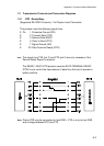
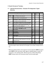
2. Parallel Centronics Interface
®
2.1 Interface Characteristics - Connector Pin Assignment / Signal
Definition
Signal Description
Pin No. Return line Direction
Pin No.
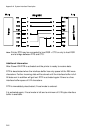
_______ Control Signal from the Host. Printer reads data line 1 19 Input
STROBE (Data 1 to Data 8) when going low.
*)
Data 1 - 8 Data lines transfer the characters from the host to 2 - 9 20 - 27 Input
the printer. Data 8 = most significant bit.
_____ Acknowledge - Negative going pulse from the printer 10 28 Output
ACKN indicates that the printer has received a character
*)
and is ready for the next data transfer.
BUSY Control signal from the printer. A high level indicates 11 29 Output
that the printer is unable to receive any more data.
**)
PE Paper Empty - Control signal from the printer. This 12 -- Output
signal goes high when paper runs out, i.e. load
upper or lower tractor, paper jam.
SELECT Control signal from the printer. A high level indicates 13 -- Output
that the printer is ON-LINE and ready.
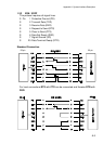
LG Logic Ground 14 --
-- not used 15 --
LG Logic Ground 16 --
CG Chassis Ground 17 --
VCC + 5 volt 18 --
SG Signal Ground 19 - 20 --
____ Control signal from the host. Does not reset the prin- 31 -- Input
INIT ter.
*)
______ Control signal from the printer. A low level indicates 32 -- Output
FAULT that the printer has been switched off, or the serial
*)
interface is active.
LG Logic Ground 33 --
-- not used 34 - 35 --
Overlined signal names indicate that the signal is true when the signal level is
*)
low.
When the interface buffer is full except for the last character, BUSY will not be
**)
reset. BUSY will be reset when buffer space is available again for least 512
characters in the interface buffer. While the printer is offline (Stop Mode)
BUSY remains active until the printer enters the online state again.