


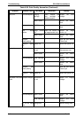
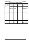


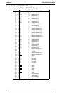
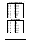
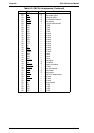
A.1 CONNECTOR PIN ASSIGNMENTS
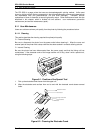
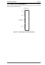
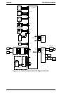
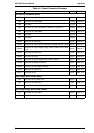
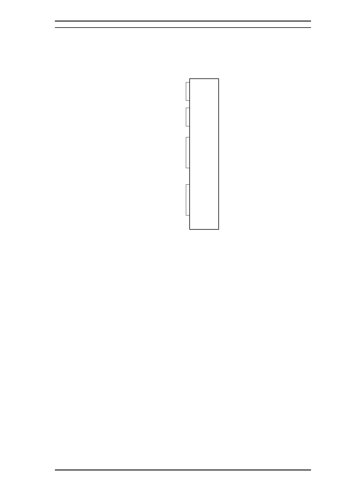
Figures A-1 and A-2 illustrate the interconnection of the primary components. Table A-1 gives the
size and a description of each connector.
CN1
Parallel I/F
CN2
RAM SIMM
CN4
LocalTalk/Serial I/F
module or Type-B EX
ROM SIMM
CN5
C169 MAIN-B Boad
Video Controller Section
Figure A-1. Connections for the Video Controller
EPL-5500 Service Manual Appendix
Rev. A A-1