


2.1.2 Engine Control
This section describes engine control, the power supply board, and the high-voltage supply board.
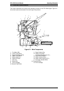
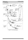
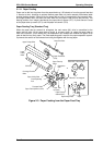
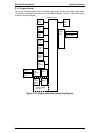
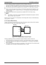
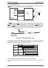
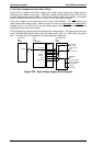
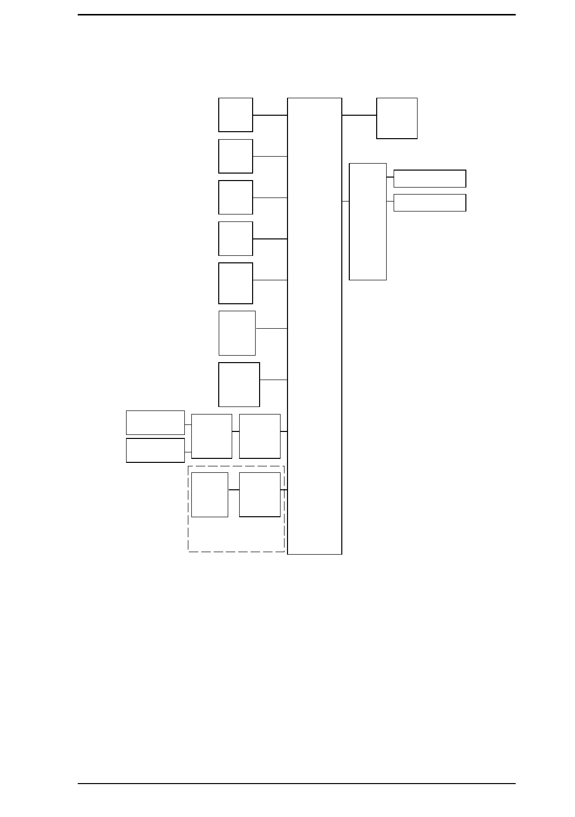
The engine is controlled by the main board (C169 MAIN-B Board). Figure 2-10 shows the engine
controller connecting diagram.
C169 MAIN-B Board
Main
Motor
(M1)
Polygon
Motor
(M2)
Fan
Motor
(M2)
Exit
Sensor
(PC3)
Paper
Take-up
Sensor
(PC1)
Paper
Take-up
Solenoid
(SL1)
Fusing
Roller
Thermistor
(TH1)
PWB-S
PWB-F
High
Voltage
Unit
Image Transfer
Housing
Image Transfer
Charger
PWB-A
Paper
Take-up
Solenoid
(SL2)
2nd Paper Feeding
Unit (Option)
PWB-D
Laser
Diode
Drive
PWB-E
Power
Unit
Heater Lamp
Interlock Switch
Figure 2-10. Engine Controller Connecting Diagram
EPL-5500 Service Manual Operating Principles
Rev. B 2-7