


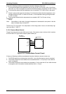
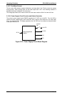
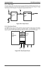
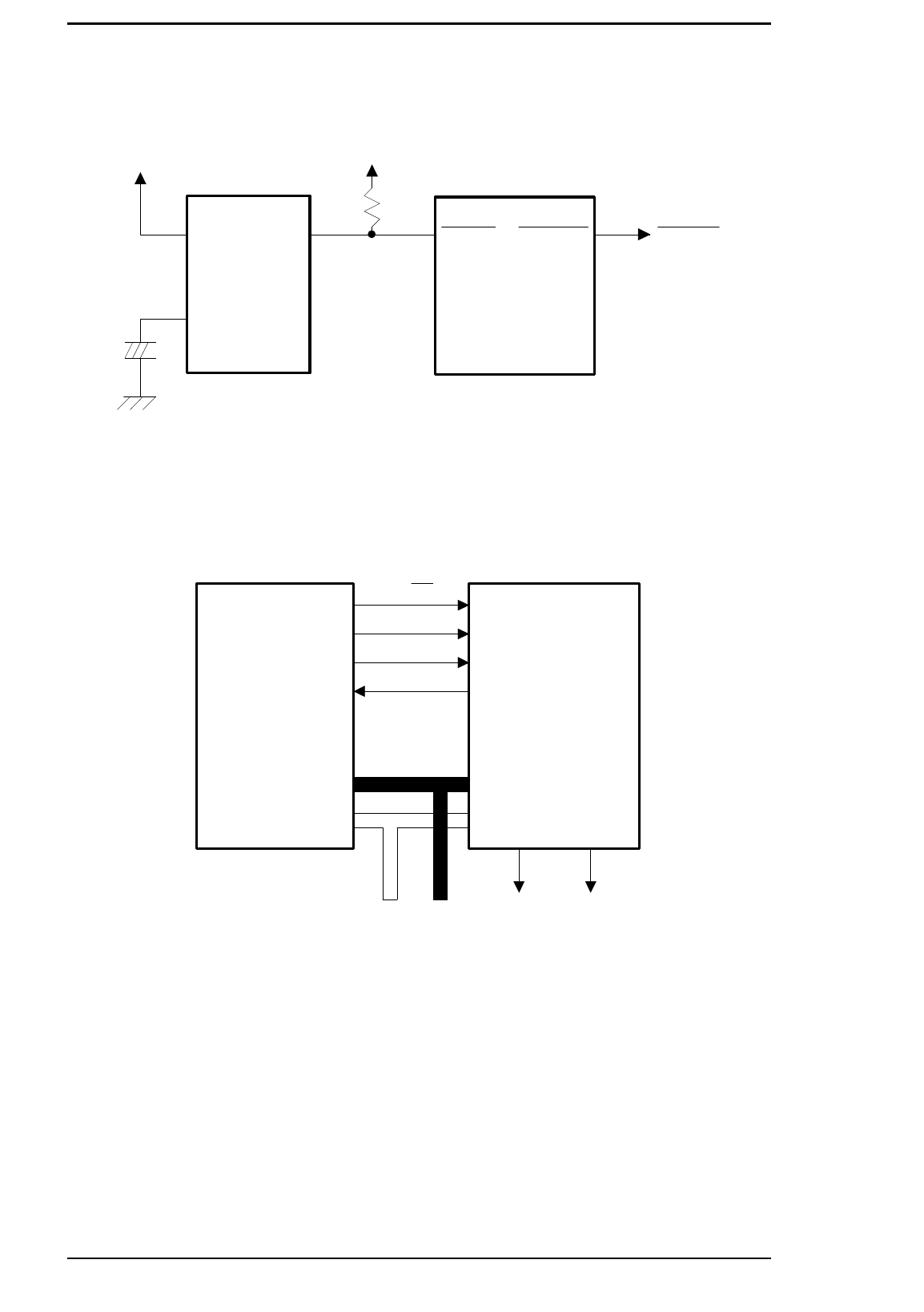
2.2.1.1 Reset Circuit
The entire system (CPU and external devices) can be initialized if the RESET signal (CPU pin 113)
are active simultaneously. This circuit uses an M51938 IC to monitor the supply voltage if a voltage
level less than 4.25 V is detected. The reset time is approximately 128 ms.
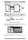
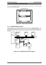
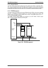
2.2.1.2 Bus Control Circuit
The MB86930 CPU outputs the R/W (read/write) signal, AS (address strobe) signal, and the BE0,
BE1, BE2, and BE3 signals (byte enables) to the ASIC E05A91. The ASIC E05A91 uses these
signals to generate the RD (read strobe) signal, WR (write strobe) signal, and READY signal.
+5 V
Vcc
+
C
OUT
+5 V
M51938FP
(IC6)
RESET
RSTOUTRSTIN
E05A92
(IC3)
Figure 2-28. Reset Circuit
R/W
AS
BE0-3
RD WR
READY
Data
Bus
Address
Bus
CPU
MB86933H
(IC1)
E05A91
(IC2)
Figure 2-29. Bus Control Circuit
Operating Principles EPL-5500 Service Manual
2-20 Rev. B