


Chapter 3 Disassembly and Assembly
Table of Contents
3.1 GENERAL INFORMATION 3-1
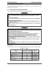
3.1.1 Precautions for Disassembly/Assembly. . . . . . . . . . . . . . . . . . . . . . . . . . . 3-1
3.1.2 Tools. . . . . . . . . . . . . . . . . . . . . . . . . . . . . . . . . . . . . . . . . . . . . . . . . . . . . . 3-1
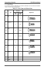
3.1.3 Small Parts . . . . . . . . . . . . . . . . . . . . . . . . . . . . . . . . . . . . . . . . . . . . . . . . . 3-2
3.1.4 Service Checks after Repair. . . . . . . . . . . . . . . . . . . . . . . . . . . . . . . . . . . . 3-3
3.2 DISASSEMBLY AND ASSEMBLY 3-4
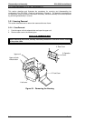
3.2.1 Housing Removal . . . . . . . . . . . . . . . . . . . . . . . . . . . . . . . . . . . . . . . . . . . . 3-4
3.2.1.1 Case Removal . . . . . . . . . . . . . . . . . . . . . . . . . . . . . . . . . . . . . . . . 3-4
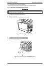
3.2.2 Removal of the Controller Section . . . . . . . . . . . . . . . . . . . . . . . . . . . . . . . 3-5
3.2.2.1 Main Board (C169 MAIN-B Board) Removal. . . . . . . . . . . . . . . . . 3-5
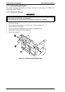
3.2.3 Disassembling the Engine . . . . . . . . . . . . . . . . . . . . . . . . . . . . . . . . . . . . . 3-6
3.2.3.1 Optical Unit Removal. . . . . . . . . . . . . . . . . . . . . . . . . . . . . . . . . . . 3-6
3.2.3.2 Image Transfer Unit Removal . . . . . . . . . . . . . . . . . . . . . . . . . . . . 3-7
3.2.3.3 Upper Unit Removal . . . . . . . . . . . . . . . . . . . . . . . . . . . . . . . . . . . 3-9
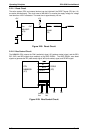
3.2.3.4 High-Voltage Supply Board (PWB-F) Removal. . . . . . . . . . . . . . 3-10
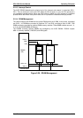
3.2.3.5 Power Supply Unit (PWB-E) Removal. . . . . . . . . . . . . . . . . . . . . 3-11
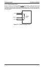
3.2.3.6 Fusing Unit Removal . . . . . . . . . . . . . . . . . . . . . . . . . . . . . . . . . . 3-12
3.2.3.7 Fusing Unit Disassembly . . . . . . . . . . . . . . . . . . . . . . . . . . . . . . . 3-15
3.2.3.8 Main Motor Removal . . . . . . . . . . . . . . . . . . . . . . . . . . . . . . . . . . 3-20
3.2.3.9 Paper Take-Up Sensor and Paper Take-Up Solenoid Removal. 3-21
3.2.3.10 Paper Take-Up Roller Removal . . . . . . . . . . . . . . . . . . . . . . . . . 3-22
List of Figures
Figure 3-1. Removing the Housing . . . . . . . . . . . . . . . . . . . . . . . . . . . . . . . . . . . 3-4
Figure 3-2. Removing the Shield Case . . . . . . . . . . . . . . . . . . . . . . . . . . . . . . . . 3-5
Figure 3-3. Removing the C169 MAIN-B Board . . . . . . . . . . . . . . . . . . . . . . . . . 3-5
Figure 3-4. Removing the Optical Unit . . . . . . . . . . . . . . . . . . . . . . . . . . . . . . . . 3-6
Figure 3-5. Removing the Image Transfer Unit -1. . . . . . . . . . . . . . . . . . . . . . . . 3-7
Figure 3-6. Removing the Image Transfer Unit -2. . . . . . . . . . . . . . . . . . . . . . . . 3-7
Figure 3-7. Moving the Image Transfer Unit . . . . . . . . . . . . . . . . . . . . . . . . . . . . 3-8
Figure 3-8. Reinstalling the Electrode Comb . . . . . . . . . . . . . . . . . . . . . . . . . . . 3-8
Figure 3-9. Removing the Harness Cover. . . . . . . . . . . . . . . . . . . . . . . . . . . . . . 3-9
Figure 3-10. Removing the Upper Unit . . . . . . . . . . . . . . . . . . . . . . . . . . . . . . . . 3-9
Figure 3-11. Removing the PWB-F Cover. . . . . . . . . . . . . . . . . . . . . . . . . . . . . 3-10
Figure 3-12. Removing the PWB-F . . . . . . . . . . . . . . . . . . . . . . . . . . . . . . . . . . 3-10
Figure 3-13. Removing the PWB-E Cover . . . . . . . . . . . . . . . . . . . . . . . . . . . . 3-11
Figure 3-14. Removing the PWB-E. . . . . . . . . . . . . . . . . . . . . . . . . . . . . . . . . . 3-11
Figure 3-15. Gear and Spring Position . . . . . . . . . . . . . . . . . . . . . . . . . . . . . . . 3-12
Figure 3-16. Removing the Fusing Guide Plate . . . . . . . . . . . . . . . . . . . . . . . . 3-12
Figure 3-17. Removing the Harness Cover. . . . . . . . . . . . . . . . . . . . . . . . . . . . 3-13
Figure 3-18. Removing the Fusing Entrance Guide . . . . . . . . . . . . . . . . . . . . . 3-13
Figure 3-19. Removing the Fusing Unit. . . . . . . . . . . . . . . . . . . . . . . . . . . . . . . 3-14
Figure 3-20. Roller Position. . . . . . . . . . . . . . . . . . . . . . . . . . . . . . . . . . . . . . . . 3-14
Figure 3-21. Removing the Heater Lamp . . . . . . . . . . . . . . . . . . . . . . . . . . . . . 3-15
Figure 3-22. Removing the Thermistor . . . . . . . . . . . . . . . . . . . . . . . . . . . . . . . 3-16
Figure 3-23. Wiring . . . . . . . . . . . . . . . . . . . . . . . . . . . . . . . . . . . . . . . . . . . . . . 3-16