


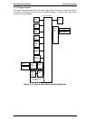

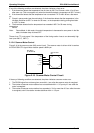
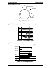
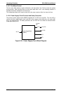
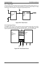
Figure 2-21 shows the print process.
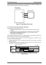
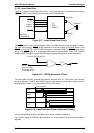
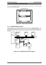
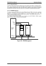
Figure 2-22 shows the start print sequence. The printer’s engine starts printing when it receives the
PRINT signal from the video controller circuit.
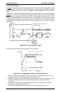
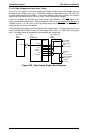
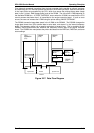
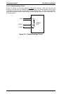
Figure 2-23 is the end of the print sequence.
Brush Roller Charging
Laser Exposure
PC Drum
Image Transfer
Development
Figure 2-21. Print Process
[m sec.]
Print
Command
Polygon Motor
(M3)
Paper Take-up
Sensor (PC1)
Paper Take-up
Solenoid
(SL1/2)
Main Motor
(M1)
Drum Charge
Laser
Exposure
Development
Image
Transfer
20
200
500
300
2310
150
500
260
1st:770, 2nd:2820
1st: 790 to 1300
2nd: 2670 to 3080
480
1st: 1510
2nd: 1680
M3 normal rotation
4000
Figure 2-22. Print Sequence (Start)
[m sec.]
Polygon Motor
(M3)
Main Motor
(M1)
Drum Charge
Laser
Exposure
Development
Image
Transfer
Paper Exit
Sensor (PC3)
5160
850
480
Figure 2-23. Print Sequence (End)
EPL-5500 Service Manual Operating Principles
Rev. B 2-15