


16 - Parts, Names and Operations
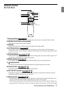
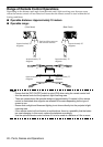
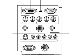
● I/O Ports
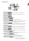
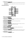
1 Computer #1 mini D-Sub 15 Port
Inputs the computer’s analog image signals.
2 Change-over Switch
Switches the valid port for Computer #1 across to either mini D-Sub15 (analog) or DVI-D
(digital). Operate the switch with the tip of a ballpoint pen or other pointed object.
3 Computer #1 DVI-D Port
Inputs the computer’s digital image signals.
4 Computer #2 BNC Port
· R/Cr/Pr · G/Y · B/Cb/Pb · H/C Sync · V Sync
Inputs the computer’s BNC image signals, the A/V equipment component image signals
(color differential signal) or the RGB image signals.
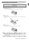
5 Remote Port
Connects the optional remote control receiver (ELPST04).
6 Mouse/Com Port
Establishes a connection with the computer when the projector software that is supplied is
to be used when the remote control is used as a wireless mouse.
7 Audio #1 Port
Inputs the audio signals from the computer and A/V equipment connected to the
Computer #1 Port.
8 S-Video Port
Inputs the A/V equipment's S image signals.
9 S-Video/Audio #2 Port
Inputs the audio signals from the computer and A/V equipment connected to the BNC
port or the S-Video port.
Outputs only the sound for connected computers and A/V equipment.
10 Video Port
Inputs the the A/V equipment’s component image signals.
11 L-Audio-R Port
Inputs the the A/V equipment’s sound signals.
12 Monitor Out Port
Outputs the projected image signals to an external monitor (not output when the input
comes from the DVI-D port.)
13 Stack Out Port
This is used during stack projection*.
Monitor Out
Stack Out
Computer 2 /
Component Video
Computer 1
Audio
Mouse/Com
S-Video S-Audio/Audio2 L-Audio-RVideo
Remote
R/Cr/Pr
B/Cb/Pb H/C Sync V SyncG/Y
3
21
4
7
11
9
13
10
8
12
5
6