


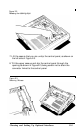
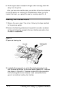

9. Lift the upper case to release the hinges at the rear edge, then lift it
away from the printer.
After you have removed the case, you can then follow the directions
in the next section on inserting the interface board. After you have
inserted the board, you replace the case by reversing steps 2 to 9.
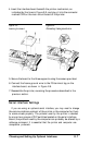
Inserting the Interface Board
1. Remove the upper case of the printer, following the steps described
in the previous section.
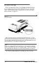
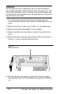
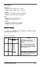
2. Remove the blanking plate above the paralle1-connector (as shown
in Figure E-4) to allow access to the new interface connector when
the case is re-assembled.
Figure E-4.
FG screw and blanking plate
3. Locate the three supports on which the interface board will rest,
and the screw at the rear of the circuit board labeled FG. These are
also shown in Figure E-4. The screw marked FG is the connection
for the frame ground wire. Unscrew it and connect the frame
ground wire before inserting the interface.
E-6
Choosing and Setting Up Optional Interfaces