


2. “Return” denotes the twisted-pair return, to be connected at signal
ground level. For the interface wiring, be sure to use a twisted-pair
cable for each signal and to complete the connection on the return
side. To prevent noise, these cables should be shielded and
connected to the chassis of the host computer or the printer but not
at both ends.
3. All interface conditions are based on TTL level. Both the rise and
the fall times of each signal must be less than 0.2 microseconds.
4. Data transfer must be carried out by observing the ACKNLG or
BUSY signal. (Data transfer to this printer can be carried out only
after receipt of the ACKNLG signal or when the level of the BUSY
signal is LOW.)
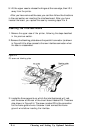
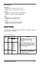
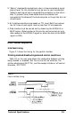
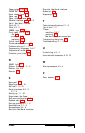
Data Transfer Sequence
Interface timing
Figure F-1 shows the timing for the parallel interface.
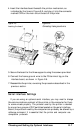
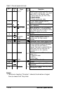
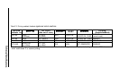
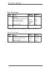
Printing enabled/disabled signals and control conditions
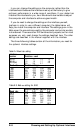
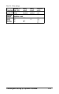
Table F-2 on the next page shows the relationship between printing
being enabled or disabled, and the on-line/off-line condition, the
printer select signal (SLCT IN),
and the receipt of data on/off control
character, DC1/DC3.
Figure F-1.
Parallel
interface timing
Technical Specifications F-5