


Installing Modules and Connecting Cables
BlackDiamond 12800 Series Switches Hardware Installation Guide
106
CAUTION
Depending on the size and complexity of your network, you should install and configure a backup MSM when
network disruption will be minimal. You may need to reboot your switch after you use the synchronize command.
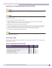
Verifying the Module Installation
After you install a module, verify that it is working correctly by checking the LEDs on the front panel of
the module. Table 23 shows normal LED operation for correctly installed MSMs and I/O modules.
Use the command line interface (CLI)
show slot <slot number> command to display slot-specific
information about the newly installed module.
For more information about LED activity, see the descriptions in Chapter 3.
Displaying Slot Status Information
Assuming the module has no problems, the command show slot <slot> (where <slot> is the number
of the slot where you installed the module) displays information about the module including: general
information about the module (name, serial number, part number), the state of the module (power
down, operational, mismatch between the slot configuration and the module in the slot), and the
number of ports on the module.
For more information about slot status information, see the ExtremeXOS 12.0 Concepts Guide and the
ExtremeXOS 12.0 Command Reference Guide.
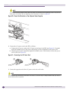
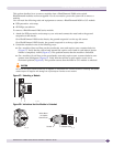
Removing a BlackDiamond 12800 Series Module
CAUTION
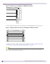
There are two styles of ejector/injector handles on the BlackDiamond 12800 series modules. Pay careful attention to
the instructions in step 2.
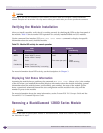
Table 23: Module LED activity for normal operation
MSM I/O Module
LED State/Meaning LED State/Meaning
SYS Green blinking STATUS Green blinking
MSTR Green: MSM is primary
Amber: MSM is backup
DIAG Off
ENV Green Port status (per port) Green
Amber blinking
Link/Activity Green: Link is up.
Amber: Packet activity is occurring.