


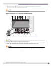

Using the BlackDiamond12804 AC Power Cord Retainer Channel
BlackDiamond 12800 Series Switches Hardware Installation Guide
85
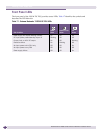
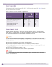
Fuse
The Extreme Networks 700/1200 W AC PSU line and neutral legs are both fused. Power to the switch
may still be live if the neutral fuse is open. This is not a field operator replaceable fuse. In the event of
failure, immediately return the Extreme Networks 700/1200 W AC PSU for a complete replacement.
WARNING!
Field operators must not attempt to configure or replace fuses in Extreme Networks 700/1200 W AC PSUs! In the
event of failure, immediately return the defective Extreme Networks 700/1200 W AC PSU for a complete
replacement.
CAUTION
The 700/1200 W AC PSU does not have a switch for turning the unit on and off. Remove the plug from the
electrical outlet to disconnect power to the 700/1200 W AC PSU. Make sure that this connection is easily
accessible.
●
Make sure that the 700/1200 W AC PSU circuit is not overloaded. Use proper over-current protection, such as a
circuit-breaker, to prevent over-current conditions.
Using the BlackDiamond12804 AC Power Cord Retainer
Channel
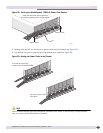
The AC power cord retaining channel for the BlackDiamond 12804 switch holds the power connectors
in the power sockets and prevents accidental disconnection due to earthquakes, vibration, or other
disturbances. A power cord retaining channel is provided with the BlackDiamond 12804 switch.
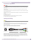
Pre-Installation Requirements
Connect all AC power cords before you install the power cord retainer channel.
You need the following tools and equipment to install or remove the BlackDiamond 12804 AC power
cord retainer channel:
● ESD-preventive wrist strap
● #2 Phillips screwdriver
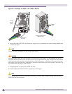
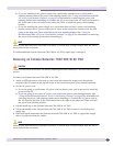
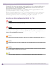
Installing the BlackDiamond 12804 AC Power Cord Retainer
Channel
To install the BlackDiamond 12804 AC power cord retainer channel:
1 Attach the ESD-preventive wrist strap to your wrist and connect the metal end to the ground
receptacle on the switch front panel.
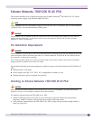
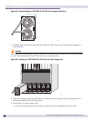
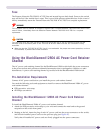
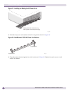
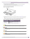
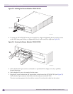
2 Starting at the left, insert the plug of each AC power cord into the power connectors on the switch,
and lift each installed power cord over the previous plug (see Figure 47).
Verify that all installed AC power cords are firmly plugged into the power connectors.