


SW DVI Plus Series • Installation 8
3. Slide the leads into the supplied 2-pole captive screw plug and secure them, using a
small screwdriver.
CAUTION: Do not tin the stripped power supply leads before attaching the captive
screw plug to them. Tinned wires are not as secure in the captive screw
connectors and can be easily pulled out. They may also break after
being bent several times.
4. To verify the polarity of the power cord before connecting it, plug in the power supply
with no load and check the output with a voltmeter.
WARNING: Keep the two power cord wires separate while the power supply is
plugged in. Remove power before wiring.
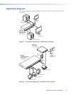
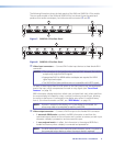
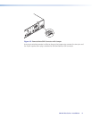
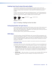
5. Use the supplied tie-wrap to strap the power cord to the extended tail of the connector.
The figure below shows how to wire the connector.
Captive Screw Connector
Tie Wrap
Heat
Shrink
1/8”
(3 mm)
7/8”
(22 mm)
3/16”
(5 mm) Max.
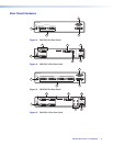
Figure 9. Power Connector Wiring
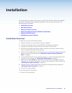
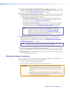
Wiring the Audio Connectors (SW DVI A Plus Models)
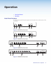
Wire the audio connectors as shown in the following diagrams.
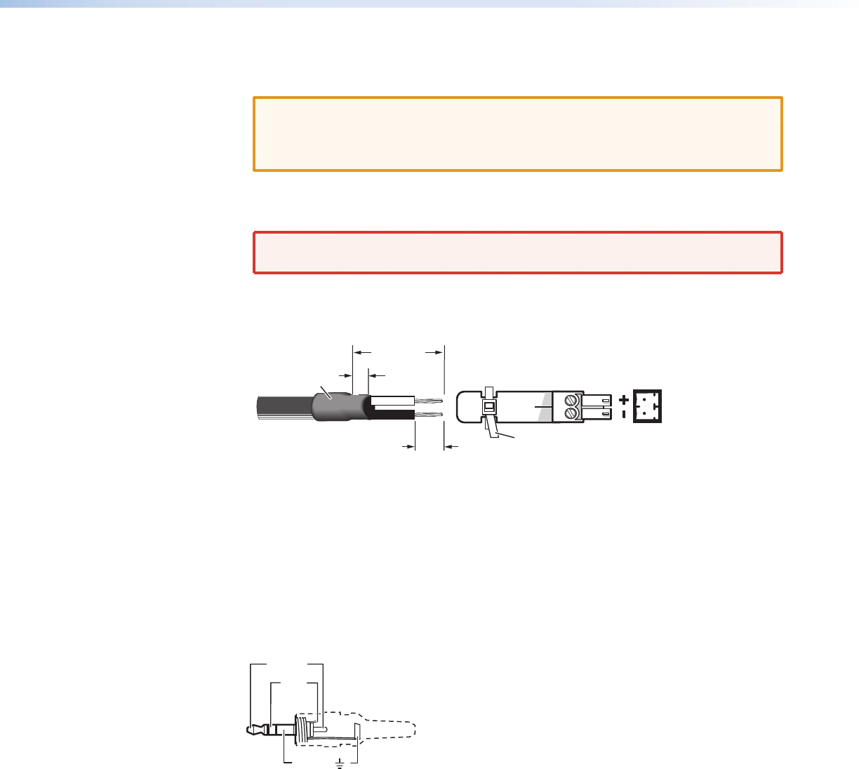
Audio Input
The SW DVI A Plus switchers have two, four, six, or eight 3.5 mm TRS audio input mini jacks
for unbalanced stereo audio. Wire the audio connectors as shown below.
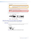
Sleeve ( )
Ring
(R)+
Tip (L)+
3.5 mm Stereo Plug Connector
(unbalanced)
Figure 10. Input Connector Pinout for Unbalanced Stereo Audio