


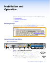
DTP T USW 233 • Installation and Operation 5
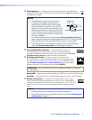
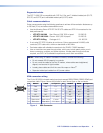
g Remote Tally port — If desired, to remotely identify the currently selected
123
TALLY
+V
input, plug a locally-constructed device into this 3.5 mm, 4-pole captive
screw connector. Connect the power wire for the device into the +V pin and
connect the ground wire for the each indicator into the corresponding tally out pin, 1, 2,
or 3.
When an input is selected, by either contact closure of front panel selection, the
corresponding tally out pin shorts to ground, closing the circuit and lighting the
connected indicator (LED).
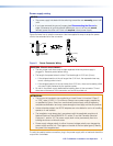
h Remote RS-232 port — Plug a serial RS-232 device into the switching
GRxTx
RS-232
transmitter via this 3.5 mm, 3-pole captive screw connector for remote control
of the switching transmitter (see IR and RS-232 connector wiring on page 8
to wire the connector).
i Reset button — The Reset button initiates two levels of reset of the switcher.
RESET
For the different reset levels, press and hold the button while the switcher is
running or while you power up the switcher (see Reset on page 11 for details).
j Power connector — Plug the included external 12 VDC power supply into either
this 2-pole connector (see Power supply wiring on page 7 to wire the connector) or
the power input connector on the receiver (see the DTP HDMI 230 User Guide on the
Extron website (www.extron.com).
NOTES:
• The power supply included with the switching transmitter can normally power
both units.
• If you have removed the ground jumpers (see Disconnecting the Ground on
page 19) because of ground potential differences, one unit of the pair cannot
remotely power the other unit. Each unit requires a local power supply.
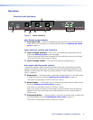
Connector and Cable Details
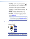
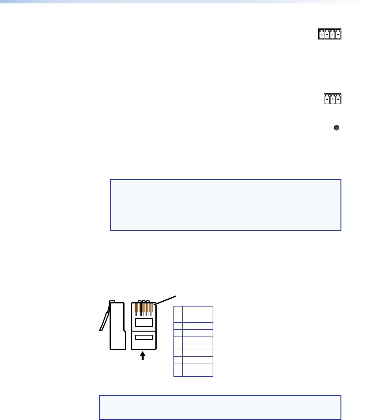
TP cable termination and recommendations
Figure 3 details the TIA/EIA T 568B wiring standard. Use this standard to terminate the
DTP cable with RJ-45 connectors.
5
Pin
1
2
3
6
7
8
4
Side
12345678
Insert
Twisted
Pair Wires
Pins:
RJ-45
Connector
Wire color
White-green
Green
White-orange
White-blue
Orange
White-brown
Brown
Blue
TIA/EIA T
568B
Figure 3. TP Cable Termination
NOTE: Do not use Extron UTP23SF-4 Enhanced Skew-Free AV UTP cable or STP201
cable to link the switching transmitter and receiver. The DTP T USW 233 Tx/Rx does
not work properly with these cables.