


DTP T USW 233 • Installation and Operation 4
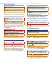
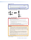
c Audio input port — If desired, plug an analog audio input into the switching
AUDIO
transmitter via this stereo mini jack connector. Analog audio is not embedded into
the digital video signal.
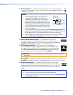
NOTES:
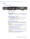
• The analog audio input on this connector is
in addition to the digital audio that may be
embedded in the HDMI inputs. See the figure
at right to identify the connector tip, ring, and
sleeve when you are making connections for the
switching transmitter from existing audio cables.
A mono audio connector consists of the tip and
sleeve. A stereo audio connector consists of the
tip, ring, and sleeve.
Sleeve ( )
Ring (
-
)
Tip (+)
3.5 mm Stereo Plug Connector
(balanced)
• If you have removed the ground jumpers (see Disconnecting the Ground on
page 19) because of ground potential differences, the DTP T USW 233 cannot
extend analog audio. The connected receiver outputs no analog audio.
• The analog audio can be assigned to a specific input or set to be always
output (see Assign analog audio SIS commands on page 15).
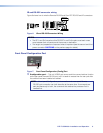
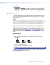
d Over DTP RS-232 and IR port — Plug a serial RS-232 signal, a
RxTx RxTxG
RS-232 IR
modulated IR signal, or both into this 3.5 mm, 5-pole captive screw
connector for bidirectional RS-232 and IR communication (see see IR and
RS-232 connector wiring on page 8 to wire the connector).
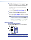
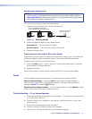
e DTP Output RJ-45 port — Plug one end of a TP cable to this
SIG LINK
DTP OUT
RJ-45 female jack on the switching transmitter. Plug the opposite end of
this cable is into the DTP Input RJ-45 connector on a compatible receiver
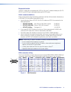
(see TP cable termination and recommendations on the next page to
properly wire the RJ-45 connector and for detailed NOTES).
ATTENTION: Do not connect this device to a telecommunications or computer
data network.
Signal LED — Lights when the unit is outputting a TMDS clock signal on the DTP output.
Link LED — Indicates a valid link is established between the units on the DTP cable.
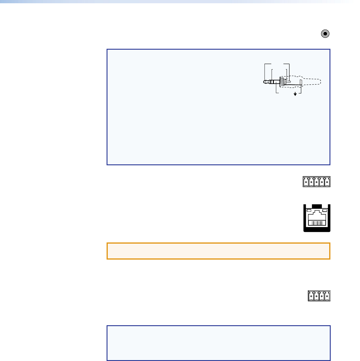
f Remote Contact port — If desired, for contact closure control, plug a
CONTACT
123G
locally-contructed contact closure device into this 3.5 mm, 4-pole captive
screw port. Momentarily short the pin for the desired input (1, 2, or 3) to G to
select that input. To force an input to be always selected, leave the short in
place.
NOTES:
• Contact closure control overrides front panel input selections.
• For contact closure control, auto switch mode must be off (see Selecting the
switch mode on page 11).