


DTP T USW 233 • Installation and Operation 9
Operation
Controls and Indications
HDCP
SIGNAL
AUTO
SWITCH
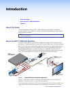
DTP T USW 233
CONFIG
1
STATUS
23
123
MODE
NORMAL
AUTO
2
7
3
1 4 5 6
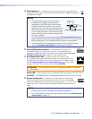
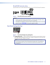
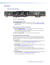
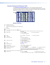
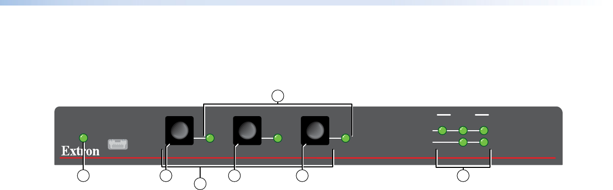
Figure 8. Power Indicators
Auto Switch mode indicator
a Auto Switch LED — When lit, indicates that the switcher is in auto-input switching
mode. When unlit, the switch is in normal (manual) mode (see Selecting the switch
mode on page 11).
Input selection controls and indicators
b Input 1 through 3 buttons — Each Input button selects the associated input for
output (see Switching inputs on the next page).
The Input buttons are also used to toggle auto-input switching mode on and off (see
“Auto-input switching mode controls,” below).
c Input 1 through 3 LEDs — The input LEDs identify the selected input.
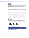
Auto-input switching mode controls
The switcher supports auto-input switching mode. When auto-input switching mode is
enabled, the switcher continuously monitors all inputs and automatically switches to the
highest-numbered input with video sync pulses present. If video is absent from all inputs,
input 1 is selected.
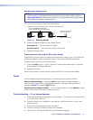
d Mode button — The Mode button is used with the Normal button or the Auto button
to select the switching mode (see Selecting the switch mode on page 11).
This button is a secondary function of the Input 1 button.
e Normal button — The Normal button is used with the Mode button to select normal
mode (see Selecting the switch mode on page 11).
This button is a secondary function of the Input 2 button.
When you change from auto-input switching to normal (manual) mode, the last input
selected in auto-input switching mode remains selected until you manually select a
different input.
f Auto(switch) button — The Auto button is used with the Mode button to select auto-
input switchinging mode (see Selecting the switch mode on page 11).
This button is a secondary function of the Input 3 button.