


DTP T USW 233 • Remote Control 14
Using the Command and Response Table
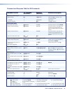
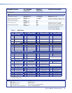
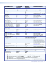
The command and response table begins on the next page. Symbols are used
throughout the table to represent variables in the command and response fields. Command
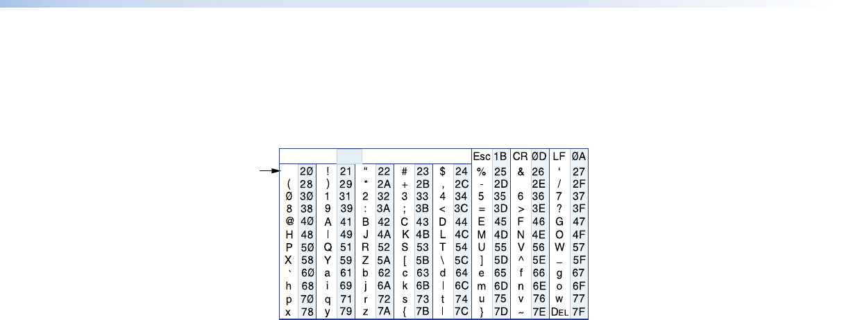
and response examples are shown throughout the table. The ASCII to HEX conversion table
below is for use with the command and response table.
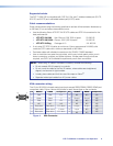
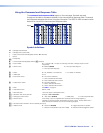
ASCII to Hex Conversion Table
•
Space
Symbol definitions
]
= Carriage return/line feed
}
= Carriage return (no line feed)
| = Pipe (can be used interchangeably with the
}
character)
• = space
E
= Escape key
W = Can be used interchangeably with the
E
character
X! = Input number 0
or
1
through
3
(
0
= no input for switching command or always output for audio
assignment)
X@ = Switch mode 0 = Manual (default) 2 = Auto-input switching low
1 = Auto-input switching high
X# = Status 0 = Off, disabled, or not detected 1 = on, enable, or detected
X$ = HDMI input 2 or 3
X% = Input HDCP status 0 = No source is detected
1 = Source is detected with HDCP
2 = Source detected without HDCP
X^ = Output HDCP status 0 = No sink is detected
1 = Sink is detected with HDCP
2 = Sink is detected without HDCP
X& = EDID See table 1 on page 16.
X* = User EDID location 66, 67, or 68
X( = Raw EDID data 128 or 256 bytes of hexadecimal data
X1) = Resolution and rate in plain text Example: 1920x1200•@60Hz
X1! = Analog input video format 0 = Auto detect (default) 1 = RGB (VGA) 2 = YUV/component video
X1@ = Switcher name A text string of up to 24 alphanumeric characters and minus sign/hyphen (-).
No blank or space characters are permitted as part of a name. The first letter must a
letter, and the last character must not be a minus sign/hyphen.
X1# = Firmware version number to second decimal place (x.xx)
X1$ = Verbose mode 0 = clear/none (default) 2 = tagged responses for queries
1 = verbose mode (default for RS-232 or USB) 3 = verbose mode and tagged for queries