


DTP T USW 233 • Installation and Operation 7
Power supply wiring
NOTES:
• The power supply included with the switching transmitter can normally power both
units.
• If you have removed the ground jumpers (see Disconnecting the Ground on
page 19) because of ground potential differences, one unit of the pair cannot
remotely power the other unit. Each unit requires a local power supply.
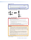
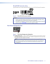
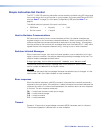
Figure 5 shows how to wire the connector. Use the supplied tie-wrap to strap the power
cord to the extended tail of the connector.
Power Supply
Output Cord
Captive Screw
Connector
SECTION A–A
Ridges
Smooth
AA
Tie Wrap
3
5
Figure 5. Power Connector Wiring
CAUTION: Electric shock hazard —
• The two power cord wires must be kept separate while the power supply is
plugged in. Remove power before wiring.
• The length of exposed wires is critical. The ideal length is 3/16 inch (5 mm).
• If the stripped section of wire is longer than 3/16 inch, the exposed wires may
touch, causing a short circuit.
• If the stripped section of wire is shorter than 3/16 inch, wires can be easily pulled
out even if tightly fastened by the captive screws.
• Do not tin the power supply leads before installing them in the connector. Tinned
wires are not as secure in the connector and could be pulled out.
ATTENTION:
• This product is intended to be supplied by a Listed Power Unit marked “Class 2”
or “LPS,” rated 12 VDC, 1.0 A minimum. Always use a power supply supplied by
or specified by Extron. Use of an unauthorized power supply voids all regulatory
compliance certification and may cause damage to the supply and the end product.
• Unless otherwise stated, the AC/DC adapters are not suitable for use in air handling
spaces or in wall cavities.
• The installation must always be in accordance with the applicable provisions of
National Electrical Code ANSI/NFPA 70, article 75 and the Canadian Electrical
Code part 1, section 16. The power supply shall not be permanently fixed to a
building structure or similar structure.
• Power supply voltage polarity is critical. Incorrect voltage polarity can damage the
power supply and the unit. The ridges on the side of the cord (see figure 5) identify
the power cord negative lead.
To verify the polarity before connection, plug in the power supply with no load and check the
output with a voltmeter.