


DTP T USW 233 • Installation and Operation 3
Installation and
Operation
This section describes the installation and the operation of the DTP T USW 233, including:
• Mounting the Unit
• Connections and Reset Button
• Operation
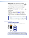
Mounting the Unit
Mounting instructions can be found in Mounting the Switcher on page 18. Compatible
optional hardware is listed on the Extron website (www.extron.com).
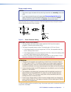
ATTENTION:
• Installation and service must be performed by authorized personnel only.
• Avoid ground potential differences between the switching transmitter and receiver
installation sites, which can lead to equipment damage or a missing or unstable
picture. If a potential difference cannot be avoided, remove the ground connection
between the units and locally power both units (see Disconnecting the Ground
on page 19). In this configuration, the DTP T USW 233 cannot extend analog audio
and the paired receiver requires its own dedicated power supply.
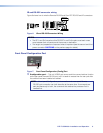
Connections and Reset Button
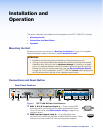
Rear Panel Features
POWER
12V
2
--A MAX
Rx GTx RxTxG
RS-232 IR
RxTx
1
RGB, Y, R-Y, B-Y HDMI HDMI
SIG LINK
DTP OUT
AUDIO
CONTACT RS-232TALLY
3
123G 123+V
RESET
INPUTS
OVER DTP REMOTE
4 6 7 8
10 3 2 2 951
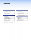
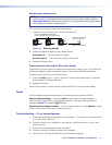
Figure 2. DTP T USW 233 Rear Panel Features
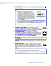
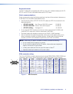
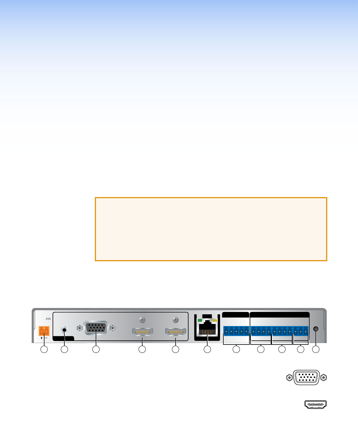
a RGB, Y, R-Y, B-Y input port (input 1) — Plug an analog (RGB
RGB, Y, R-Y, B-Y
and component) video source into the switching transmitter via this
15-pin HD connector. See VGA connector wiring on page 6 to for
connector pinout.
b HDMI input port (input 2 and 3) — Plug HDMI digital video
HDMI
sources into the switching transmitter via these HDMI connectors. These
connectors can also accept DVI video with appropriate adapters.