


DTP T USW 233 • Installation and Operation 10
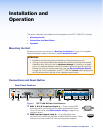
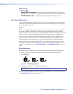
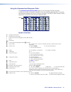
Status LEDs
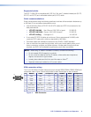
g Status LEDs —
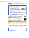
Signal LEDs (1 through 3) — Indicates that the switcher detects Horizontal sync
(Signal LED 1) or TMDS clock (Signal LED 2 and Signal LED 3) on the associated input.
HDCP LEDs (2 and 3) — Indicates that the input signal is HDCP encrypted.
Front Panel Operations
The following paragraphs detail the power up process and provide sample procedures for
switching inputs, changing between normal and auto-input switching mode, and toggling
executive mode on and off.
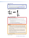
Power
Power is automatically applied when the power cord is connected to an AC source. When
AC power is applied, the switcher performs a self-test that blinks the front panel LEDs
during the test. An error-free power up self-test sequence leaves the Auto Switch and Input
LEDs on or off in the same configuration as they were when power was last removed.
If an error occurs during the self-test, the switcher locks up and will not operate. If your
switcher locks up on power-up, call the Extron S3 Sales & Technical Support Hotline.
Plug in all system components and turn on the input devices (such as Blu-Ray players
and computers) and the output devices. Set the input devices to output video using the
operating instructions of that device. Select an input. The image should appear on the
screen. If no image appears, see Troubleshooting — If No Image Appears on the next
page.
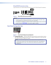
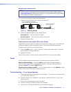
Switching inputs
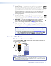
Select an input for transmission to the receiver using the front panel buttons as follows:
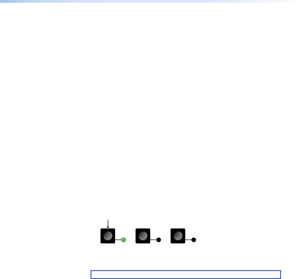
1. Select the desired input by pressing the associated input button (see figure 9).
1
23
MODE
NORMAL
AUTO
Press the button.
The LED lights
green.
Figure 9. Selecting an Input
2. Observe that the LED for the selected input lights.
NOTE: The switcher must be in normal (manual) mode.
An input can also be selected using an RS-232 or USB device or a contact closure device
(see Remote Control, beginning on page 12).