


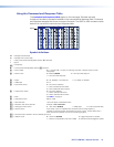
DTP T USW 233 • Remote Control 17
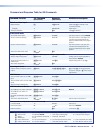
Command Function
SIS Command
(Host to Unit)
Response
(Unit to Host)
Additional description
Input 1 (only) video format
Set format
1*
X1!
\ Typ
X1!]
Set input 1 to format
X1!
.
Example:
1*0\
Typ0
]
Set input 1 to autodetect.
View format
1\
X1!]
View set format.
View detected format
1*\
X1!]
View detected format (
X1!
= 1 or 2 only).
Video mute
Mute video
1B
Vmt1
]
Output no video signal.
Unmute video
0B
Vmt0
]
Output selected video input.
Read video mute
B
X#]
Mute status =
X#
.
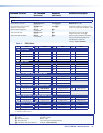
Analog audio mute
Mute analog audio
1Z
Amt1
]
Output no analog audio signal.
Unmute analog audio
0Z
Amt0
]
Output analog audio input.
Read analog audio mute
Z
X#]
Analog audio mute status =
X#
.
Disable (Mute) HDMI Output Embedded Audio
Enable HDMI audio output
E
1AFMT
}
Afmt1
]
Enable HDMI audio. (Default)
Disable HDMI audio output
E
0AFMT
}
Afmt0
]
Disable HDMI audio.
View HDMI audio configuration
E
AFMT
} X#]
Device Name
Set the unit name
EX1@
CN
}
Ipn
•
X1@]
Change the name to one of your choosing.
Set unit name to factory default
E
•
CN
}
Ipn
•
DTP-T-USW-233
]
Set name to default.
View unit name
E
CN
} X1@]
Reset
Reset to factory setting
E
ZXXX
}
Zpx
]
Reset to factory defaults.
Reset to factory setting and device
name
E
ZQQQ
}
Zpq
]
Reset to factory defaults, including,
default name (
DTP-T-USW-233).
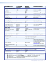
Information requests
Information request
I
In
X!
•
Aflw
X!
•
Ausw
X@
•
Vmt
X#
•
Amt
X#]
Example:
I
In1
•
Aflw2
•
Ausw1
•
Vmt1
•
Amt0
]
Input 1 is selected, analog audio is
assigned to input 2, the switcher is in
auto-input switching (high) mode, video
is muted and analog audio is unmuted.
Request part number
N
60-nnnn-nn
]
See the Extron website,
www.extron.com, for part numbers.
Query controller firmware version
Q
X1#]
Example:
Q
1.23
]
The factory-installed controller firmware
version is 1.23 (sample value only).
Verbose mode
NOTE: If tagged responses are enabled (modes 2 and 3), all “view” commands return the prefix and the value, just as the “set”
commands do. For example, the View front panel switch mode (
E
AUSW
}
) command returns “Ausw
X@]
“.
Set verbose mode
EX1$
CV
}
Vrb
X1$]
Read verbose mode
E
CV
} X1$]
NOTE:
X!
= Input number 0
or
1
through
3
(
0
= always output for audio assignment)
X@
= Switch mode 0 = Manual (default) 1 = Auto-input switching high 2 = Auto-input switching low
X#
= Status 0 = Off, disabled, or not detected 1 = on, enable, or detected
X1!
= Analog input video format 0 = Auto detect (default) 1 = RGB (VGA) 2 = YUV/component video
X1@
= Switcher name A text string of up to 24 alphanumeric characters and minus sign/hyphen (-).
X1#
= Firmware version number to second decimal place (x.xx)
X1$
= Verbose mode 0 = clear/none (default) 2 = tagged responses for queries
1 = verbose mode (default for RS-232 or USB) 3 = verbose mode and tagged for queries