


DTP T USW 233 • Installation and Operation 8
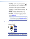
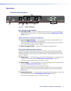
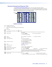
IR and RS-232 connector wiring
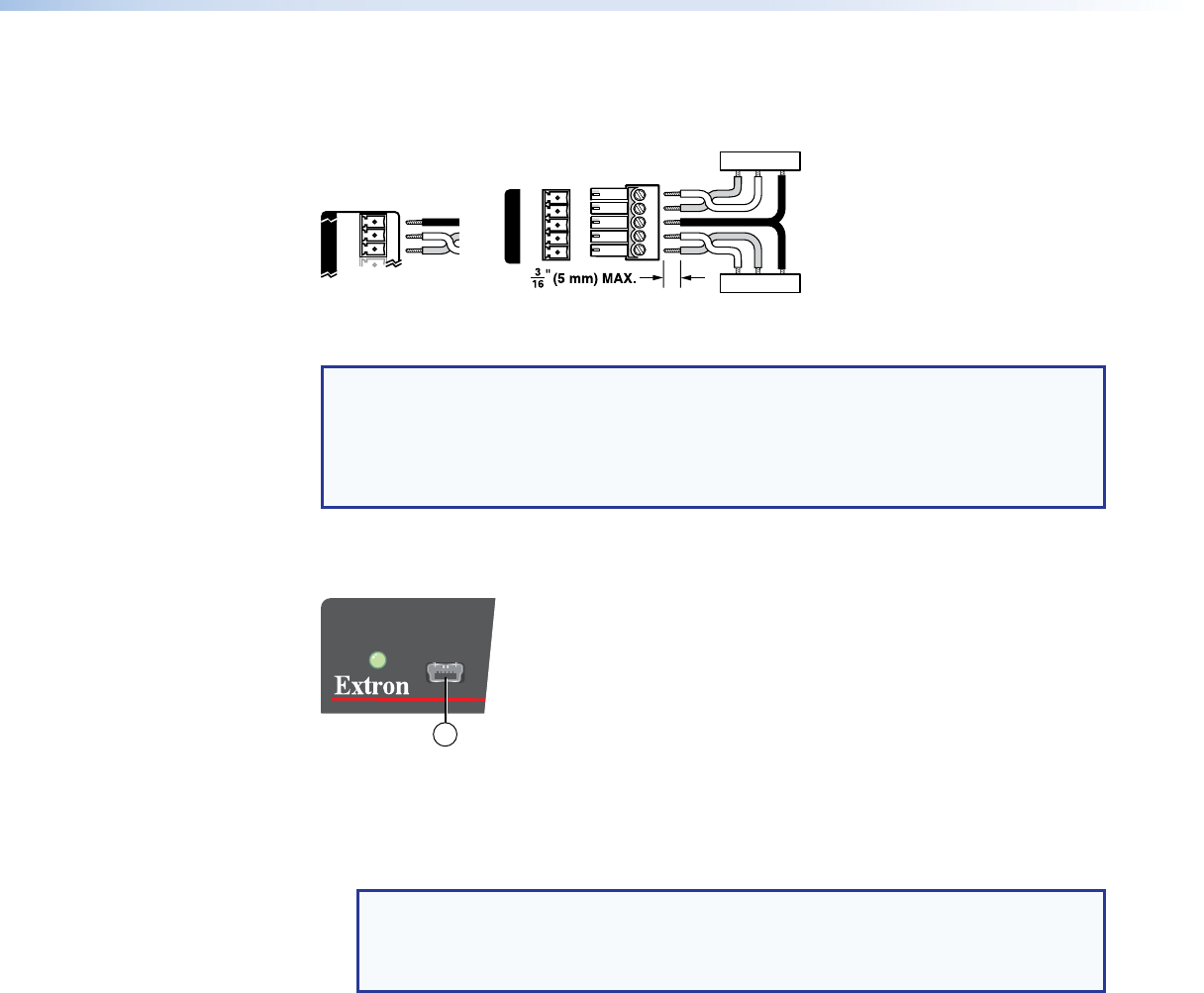
Figure 6 shows how to wire the Remote RS-232 and Over DTP RS-232 and IR connectors.
TxRx
RxTx
Gnd
Gnd
IR Device
RS-232 Device
Rx
G
Tx RxTxG
RS-232 IR
RxTx
RS-232
V
OVER DTP
REMOTE
Figure 6. IR and RS-232 Connectors Wiring
NOTES:
• The IR Tx and Rx line pair and the RS-232 Tx and Rx line pairs must each cross
once between their connectors and the source or destination.
• The length and preparation of exposed wires is important (see the second and third
power connector CAUTIONS on the previous page for details).
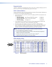
Front Panel Configuration Port
AUTO
SWITCH
CONFIG
1
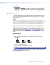
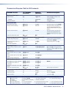
Figure 7. Front Panel Configuration (Config) Port
a Configuration port — This mini USB B port serves a similar communications function
as the rear panel Remote RS-232 port, but it is easier to access than the rear port after
the switcher has been installed and cabled.
NOTE: A front panel Configuration port connection and a rear panel Remote
RS-232 port connection can both be active at the same time. If commands are
sent simultaneously to both, the command that reaches the processor first is
handled first.