


Extron • Matrix 3200/6400 Series • User’s Manual
Chapter 3 • Tutorial - Using the Matrix 3200/6400 System Virtualization/Control Software
Switching does; it groups physical input connectors and physical output
connectors together into
Virtual Inputs
and
Virtual Outputs
, each of which
switches from 1 to 6
Virtual Planes.
Let’s carry the S-Video example a step further using the 64 x 64 Video BME and
a 64 x 64 Audio BME. If we can
map
(logically split) the first box into a ‘Y’ plane
and a ‘C’ plane and the second box into an ‘Audio’ plane, we will have created a
system with 32 Virtual Inputs and 32 Virtual Outputs in 3 Virtual Planes. [The 32
comes from splitting the 64 x 64 Video box into two halves]. In this example, half
of the Audio box would not be included in the Virtual map since we only need 32
of the 64 ports and we’d be better off using a 32 x 32 Audio BME for this
configuration. Or, using the same hardware, we could map the first box as
‘Composite Video’ and the second into an ‘Audio’ plane again to create a system
of 64 Virtual Inputs and 64 Virtual Outputs in 2 Virtual Planes. Or, we could map
the first box into ‘Component Video’ with a ‘R-Y’ plane, a ‘B-Y’ plane, and a ‘Y’
plane and the second into an ‘Audio’ plane again to create a system of 21 Virtual
Inputs and 21 Virtual Outputs in 4 Virtual Planes. [The 21 comes from splitting
the 64 x 64 Video box into three parts]. All three of these configurations are made
with the same two BMEs merely by loading the appropriate Virtual Map into the
Matrix 3200/6400 system’s memory.
Note that the number of Virtual Planes tells you how many physical input (or
output) connectors will be switched together for each Virtual Input (or Output)
switched. In the 21 x 21 x 4 Component Video with Audio virtual system example,
the first BME might have physical inputs 1, 2, and 3 as Virtual Input 1 and 4, 5,
and 6 as Virtual Input 2, etc. The Audio BME would have physical input 1 as
Virtual Input 1, 2 as 2, etc.
The Windows Virtualization/Control Program is used to create and load the Virtual
Map to the Matrix 3200/6400 system as described in the Creating a Virtual I/O
Switching System (Map) for the Matrix 3200/6400 System section.
Creating a VIRTUAL I/O SWITCHING SYSTEM (MAP) for the Matrix 3200/6400 System
The following steps use the Windows Virtualization/Control Program to create a
Virtual I/O Switching System (click here for definitions) within the physical
hardware by generating and loading a
map
to the Matrix 3200/6400 hardware. A
physical Matrix 3200/6400 System consists of from 1 to 6 Switcher boxes
(BMEs), each of which may have as many as 64 inputs and 64 outputs. After
determining what type and sizes of switcher hardware exists in the matrix, the
program will generate a ‘virtual system’ consisting of from 1 to 64
Virtual Inputs,
and 1 to 64
Virtual Outputs
, in 1 to 6
Virtual Planes.
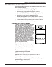
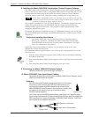
• Ensure that all BME’s that
will be part of the system
have been connected to
each other and their BME
numbers have been set
correctly. Establish an
RS-232 connection between
the PC and BME #0 of the
Matrix 3200/6400 System.
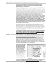
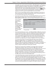
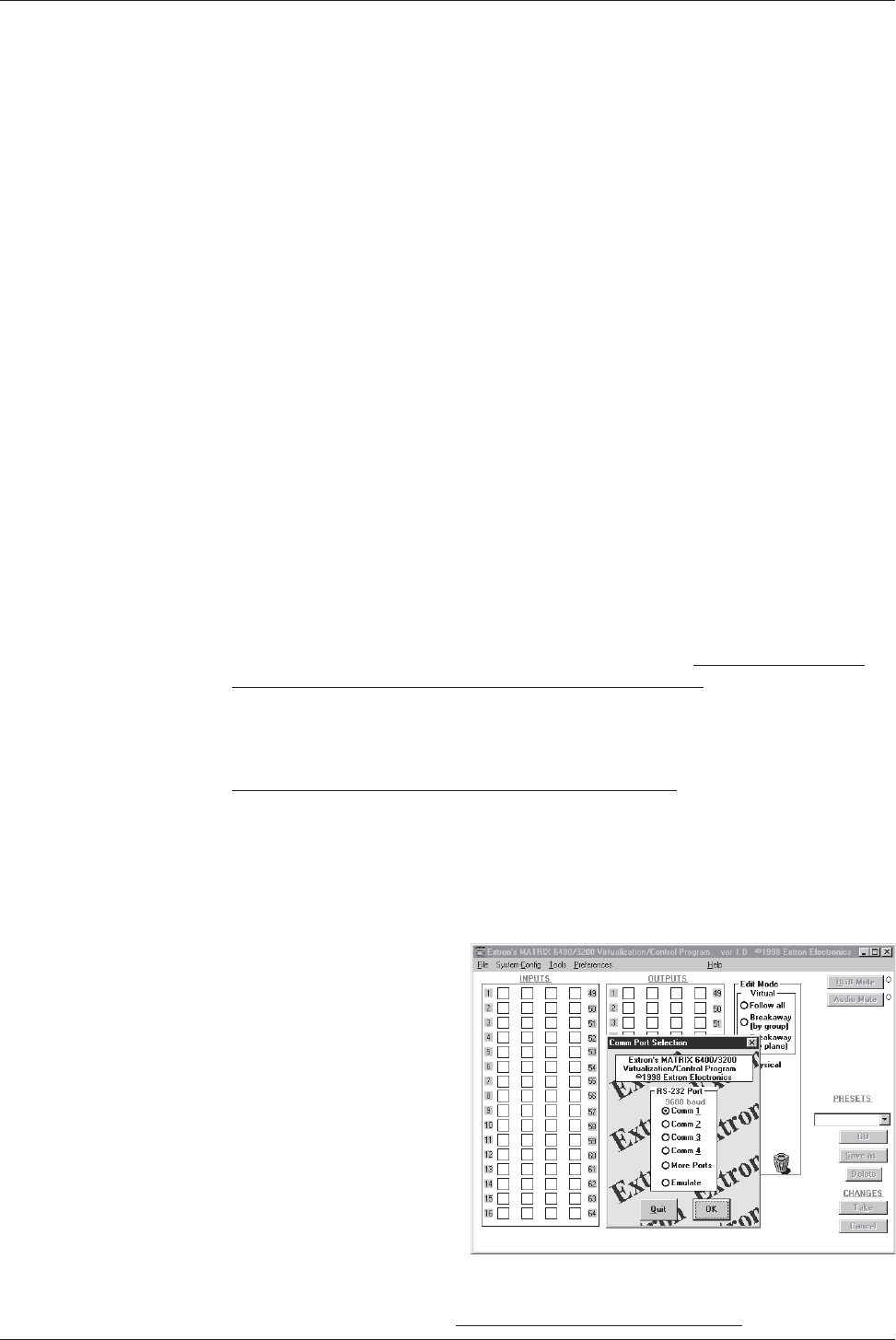
Start the MTRX6400
program (under Windows)
and click on the
corresponding COMM PORT
number when asked (Figure
3-2.A). Click OK, or.....
If you wish to program a system without being connected to it at this time, click
on EMULATE. Follow steps in How to Off-Line (Emulate) Program the Matrix.
3-2
FIGURE 3-2.A