


Extron • Matrix 3200/6400 Series • User’s Manual
Chapter 5 • Upgrades and Troubleshooting
5-8
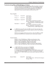
AC POWER INPUT
FUSE: 250V 5.0A TT
IN
OUT
100-240V 5.0A MAX 50/60Hz
DISCONNECT POWER CORD BEFORE SERVICING
MKP COMM.BME COMM. RS232/RS422
A
B
C
D
E
A
B
C
D
E
BME
ADDRESS
ANAHEIM, CA
MADE IN USA
4
-
+
INPUTS OUTPUTS
OUT OUT OUT OUT OUT OUT OUT OUT
1 - 8 9 - 16 17 - 24 25 - 32 33 - 40 41 - 48 49 - 56 57 - 64
1IN
SYNC
OUT
9 172533414957
2 10182634425058
3 11192735435159
4 12202836445260
5 13212937455361
6 14223038465462
7 15233139475563
8 16243240485664
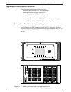
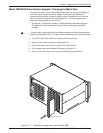
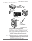
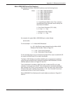
Determining Video Output Card Population
The drawings above show the rear panel layout for the
Matrix 3200 and Matrix 6400 Video Switchers. The
number of input connectors is fixed at 32 or 64; the
number of output connectors depends on the number of
Video Output cards and is variable from 8 to 32 or 64 in
multiples of 8. Each card supports 8 video outputs and
each card slot is labeled to identify the physical
connector range supported by the card in that slot (low
number = top connector, high number = bottom
connector on card).
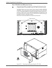
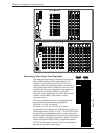
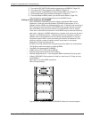
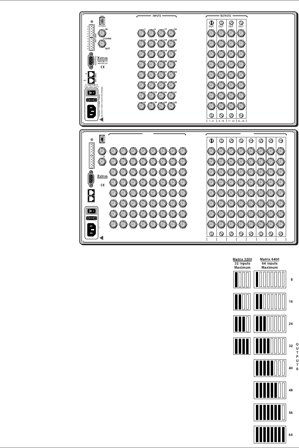
The chart to the right shows the only supported Video
card population for the following configurations.
32 inputs x 8, 16, 24, 32 outputs
64 inputs x 8, 16, 24, 32, 40, 48, 56, 64 outputs
An example matrix configuration of 64x40 would require five
Video Output cards in slots 1-8, 9-16, 17-24, 25-32 and 33-40.
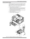
If the cards are not installed as shown for each matrix size,
the Extron Matrix 6400 System Virtualization/Control Software
will be unable to accurately virtualize the system. The Video
Output circuit cards (PN# 70-068-01) plug into connectors
OUTPUTS 1-8 through 25-32 or 57-64. It is not possible to
plug the circuit cards in upside down.