


Extron • Matrix 3200/6400 Series • User’s Manual
Chapter 4 • Programmer’s Guide
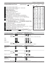
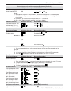
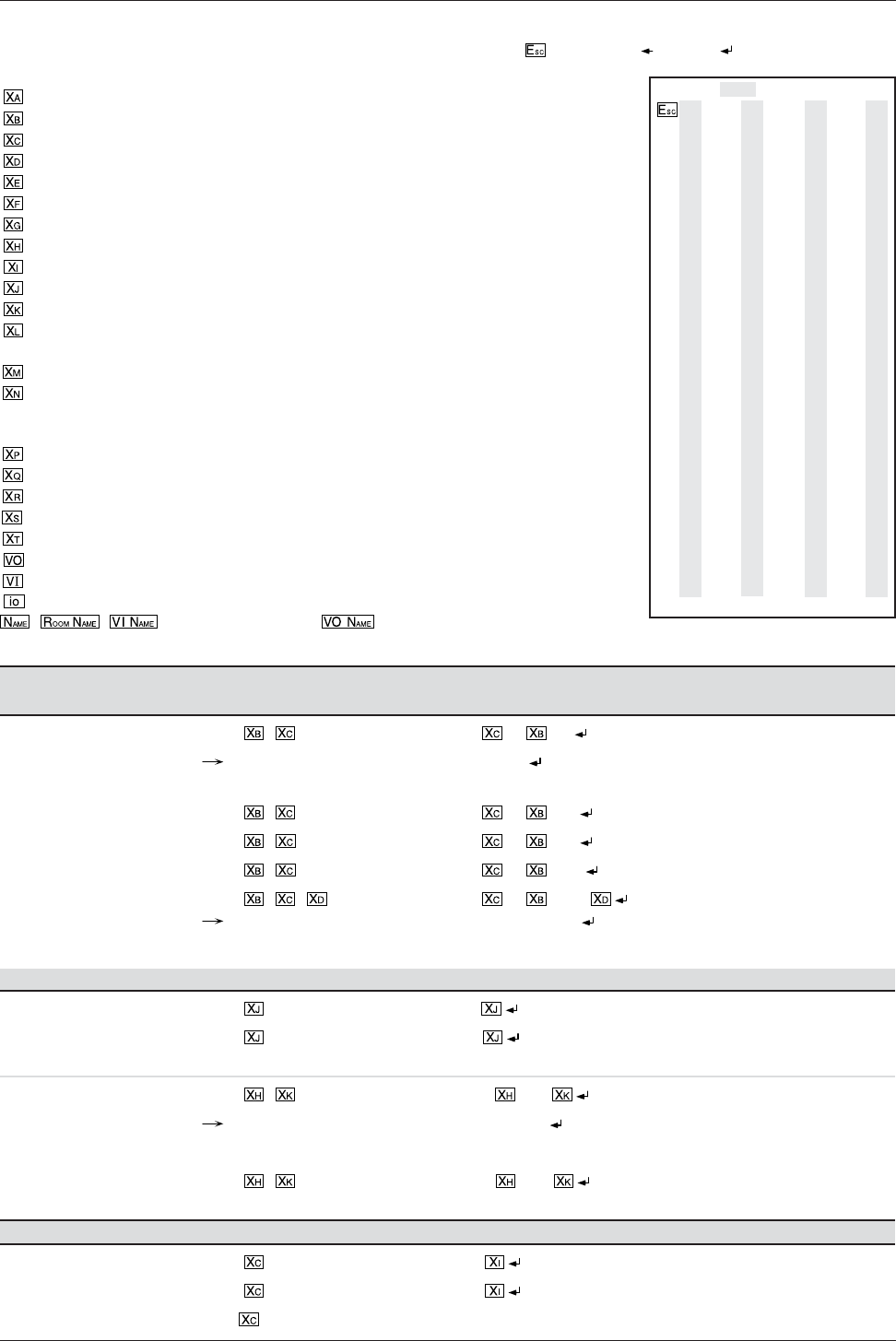
SIMPLE INSTRUCTION S ET C OMMANDS (PAGE 1 OF 3)
OUTPUT S WITCHING C OMMANDS ASCII (HOST-SWITCHER) RESPONSE (SWITCHER-HOST)
All
* ! Out •In •All
Example 3*21! Out21•In
Ø
3
Example explanation: Connect Virtual Output 21 to Virtual Input 3 in all Planes (i.e. Audio Follows Video).
RGB * & Out •In •Vid
Video * % Out •In •Vid
Audio * $ Out •In •Aud
Specific BME * * ! Out •In •Bme
Example 11*2*2! Out
Ø
2•In11•BME
Ø
2
Example explanation: Connect physical Output 2 in BME 2 to physical Input 11 in BME 2.
PRESET C OMMANDS ASCII (HOST-SWITCHER) RESPONSE (SWITCHER-HOST)
Save Current
, Spr
Recall . Rpr
Save for a room * , Rmm •Spr
Example 3*9 Rmm
Ø
3•Spr
Ø
9
Example explanation: Save Current Ties as Preset #9 for Room #3.
Recall for a room * . Rmm •Rpr
RGB MUTE COMMANDS ASCII (HOST-SWITCHER) RESPONSE (SWITCHER-HOST)
RGB Mute
B Vmt
RGB Un-mute b Vmt
Note: Where
is not included, global RGB mute is activated.
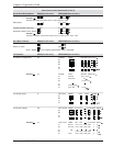
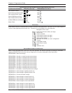
COMMAND/RESPONSE TABLE
= 1 thru maximum number of inputs
=
Ø
thru maximum number of inputs (Input
Ø
= muted output)
= 1 thru maximum number of outputs
= BME number (
Ø
thru 5)
=
Ø
dB thru 9 dB (audio gain)
= 1 dB thru 15 dB (audio attenuation)
= Numerical Value –15 thru +9
= 1 thru maximum number of rooms [1
Ø
max.]
=
Ø
or 1 (
Ø
meaning off and 1 meaning on)
= Global preset # (
Ø
= current ties for system in view) [32 max.]
= Room preset # (
Ø
= current ties for room in view mode) [1
Ø
max.]
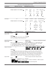
= Group Mode (follow). A = All (Follow), B = Aud / Vid / RGB breakaway,
C = total breakaway
= Delay in ½ second increments [1
Ø
max. = 5.
Ø
seconds]
= One digit status of Main and Redundant Power Supplies
Ø
= Off or Dead Power supply 1 = No Redundant, using Main Power
2 = Using Redundant Power supply 3 = Has Redundant, using Main Power
= 1 through maximum number of virtual planes
=
ØØ
through 99 (two digits)
= (Y)es or (N)o, Y = Mute and N = UnMute for RGB or Audio
= Controller software version to the second decimal place
=
Ø
= No mute, 1 = Video mute, 2 = Audio mute, 3 = Vid. & Aud. mute, – = Not used
= Two digit Virtual output number [16 per room max]
= Two digit Virtual input number
= Four character physical i/o port (BME# + i or o + port#) example 3i
Ø
7
, , (Virtual Input Name), (Virtual Output Name) = Maximum
of 12 alphanumeric characters (upper and lower case) “ ” + - : = / and space.
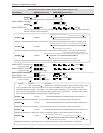
Symbol Definitions:
= Escape = CR = CR/LF • = space
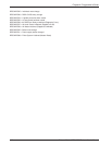
ASCII to HEX Conversion Table
1B CR
Ø
DLF
Ø
A · 2
Ø
! 21 “ 22 # 23 $ 24
% 25 & 26 ‘ 27 ( 28
) 29 * 2A + 2B , 2C
- 2D . 2E / 2F
Ø
3
Ø
1 31 2 32 3 33 4 34
5 35 6 36 7 37 8 38
9 39 : 3A ; 3B < 3C
= 3D > 3E ? 3F @ 4
Ø
A 41 B 42 C 43 D 44
E 45 F 46 G 47 H 48
I 49 J 4A K 4B L 4C
M 4D N 4E O 4F P 5
Ø
Q 51 R 52 S 53 T 54
U 55 V 56 W 57 X 58
Y 59 Z 5A [ 5B \ 5C
] 5D ^ 5E _ 5F ` 6
Ø
a 61 b 62 c 63 d 64
e 65 f 66 g 67 h 68
i 69 j 6A k 6B l 6C
m 6D n 6E o 6F p 7
Ø
q 71 r 72 s 73 t 74
u 75 v 76 w 77 x 78
y 79 z 7A
{
7B
|
7C
}
7D
~
7E
DEL
7F
4-3