


Extron • Matrix 3200/6400 Series • User’s Manual
Chapter 4 • Programmer’s Guide
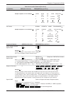
Serial Communications Port
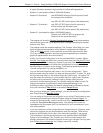
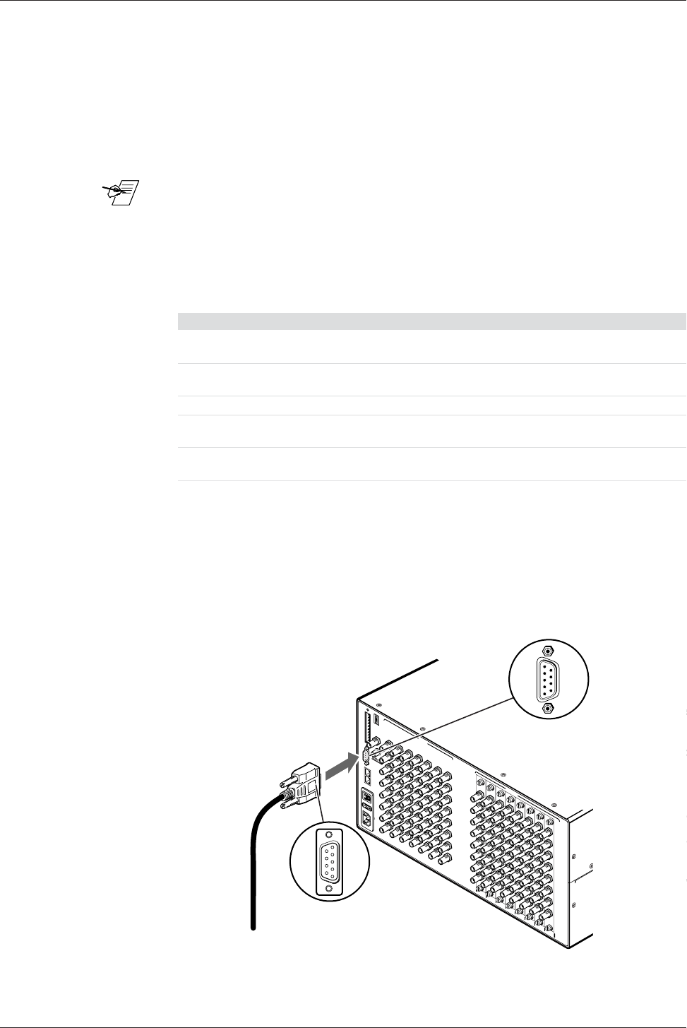
If the Matrix Video Switcher is the Master BME (BME #0), its RS-232/RS-422
connector may be connected to the serial port output of a Host device such as a
computer or control panel. Software control of the switcher is made possible by
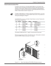
this connection. A Host serial port connection to the RS-232/RS-422 connector of
a Matrix Video Switcher is shown in Figure 4-1.A.
___ The Matrix Video Switcher is normally configured for RS-232 control. If it is to be
used with an RS-422 device, an internal cable must be moved. The procedure for
moving the cable begins on Page 5-1.
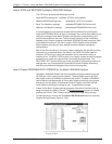
The RS-232/422 connector on the Matrix Video Switcher is a 9-pin D female with
the following pin assignments:
Pin RS-232 Description RS-422 Description
1 – not used Tx(-) Transmit Data (-)
2 Tx Transmit Data Tx(+) Transmit Data (+)
3 Rx Receive Data Rx(+) Receive Data (+)
4 – not used Rx(-) Receive Data (-)
5 Gnd Signal Ground Gnd Ground
6 – not used – not used
7 – not used – not used
8 – not used – not used
9 – not used – not used
The protocol is 9600 baud, 8-bit, 1 stop bit, no parity and no Flow control.
Details for programming the Matrix Video Switcher from a Host system connected
to the RS-232/RS-422 port are covered in this chapter.
4-1
Figure 4-1.A Matrix Video Switcher RS-232/RS-422 to Host connection.
A
N
A
H
E
I
M
,
C
A
M
A
D
E
I
N
U
S
A
A
C
P
O
W
E
R
IN
P
U
T
F
U
S
E
: 2
5
0
V
5
.0
A
T
T
100-240V 0.5A MAX 50/60Hz
DISCONNECT POWER CORD BEFORE SERVICING
B
M
E
A
D
D
R
E
S
S
4
IN
O
U
T
BME COMM.
MKP COMM.
A
B
C
D
E
A
B
C
D
E
To Host
System/Device
Serial Port
Male
Connector
1
5
6
9
I
N
1 - 8
I
N
9 - 1
6
1
7
- 24
2
5
- 3
2
33
- 4
0
41
- 48
4
9 - 56
57 - 6
4
INP
U
TS
O
UTP
UT
S
Female
Connector
1
5
6
9