


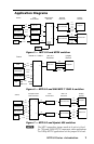
Introduction, cont’d
MTP U R Series • Introduction
6
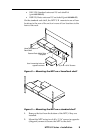
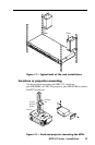
6. If applicable, reinstall the receiver and reconnect all cables.
N
Jumper 1 should be set to uni-directional when an
MTP DA is installed as part of the system to avoid any
RS-232 /Audio detection issues.
When an MTP U R series receiver is used with an
MTPX Matrix Switcher, it should be set to
unidirectional for transmitter to receiver communication,
otherwise it should be set to bi-directional when using
the RS-232 output insert connections on the switcher.
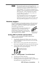
Setting the jumpers to positive vertical and/or
horizontal sync polarity
Jumper 2 is the controlling jumper for vertical sync, and
Jumper 3 for horizontal sync. Jumpers 2 and 3 are to the left of
Jumper 1, when viewed from the rear of the receiver. By default
they are set to open (1 pin covered). They can be repositioned to
invert vertical or horizontal sync as follows:
1. If the unit is not already open, follow steps 1 and 2 on the
previous page to access the jumpers.
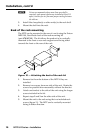
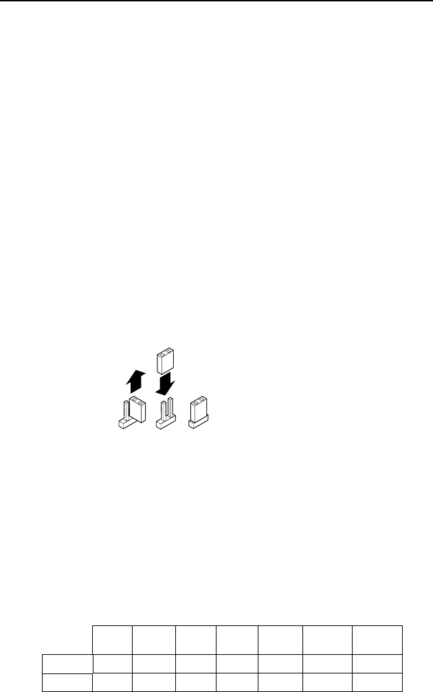
2. Locate JMP 2 and JMP 3 on the main board. Remove and
reposition the jumper block over both pins (see figure 4).
Reposition the jumper
block to cover both pins.
Figure 4 — Inverting sync with jumpers 2 and 3
3. Follow steps 4 through 6 on the previous page.
To reset the syncs to default, open the unit and turn the
applicable jumper block to cover only a single pin, as desired.
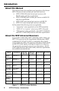
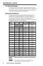
Transmitter Jumper
When using the MTP T 15HD series products with the
MTP U R, the bi/tri-level sync jumper on the transmitter should
be set as follows when transmitting component video.
480i 480p 576i 576p 720p 1080i 1080p
Bi-level X X X X X
Tri-level X X