


MTP U R Series • Installation
Installation, cont’d
14
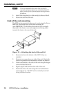
a
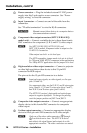
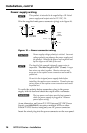
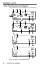
Power connector — Plug the included external 12 VDC power
supply into this 2-pole captive screw connector. See “Power
supply wiring” to wire the connector.
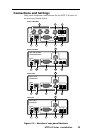
b
Input 1 connector — Connect one end of the cable from the
transmitter.
See “TP cable termination” to wire the RJ-45 connectors.
C Do not connect these devices to a computer data or
telecommunications network.
c
Component video output connectors (MTP U R RSA SEQ
model only) — Connect a suitable device to these three female
BNC connectors for component (Y, R-Y, and B-Y) video output.
N
For MTP U R RS SEQ, MTP U R RS, and
MPT U R A models, component video is output on the
15-HD VGA connector.
Video output can be bi- or tri-level sync.
The MTP transmitter jumper needs to be set to tri-level
for 720p and 1080i HDTV component video applications
For 1080p HDTV applications set the jumper to bi-level.
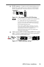
d
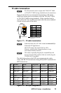
High resolution video output connector — Connect a projector
or other high resolution video device to this 15-pin HD
connector for RGB output.
The pin-out for the 15-pin HD connector is as below
N
Input only sync signals, no video signals, on the sync
pins (13 and 14).
For component video, use the R (R-Y) and R return pins
(pins 1 and 6), G (Y) and G return pins (pins 2 and 7),
and B (B-Y) and B return pins (pins 3 and 8).
The MTP U R receiver’s horizontal and vertical sync
output is negative by default. To change the polarity,
reset the jumper position on JMP 2 and JMP 3.
e
Composite video output connector — Connect an appropriate
display device to this female BNC connector for composite
video output.
f
S-video output connector — Connect an appropriate display
device to this 4-pin mini DIN connector for S-video output.
N
Only one of the above video connectors (
c
through
f
) can be active at a time. The MTP U R device
auto detects the signal format and outputs it on the
appropriate connector. The other connectors are muted.