


MTP U R Series • Installation
19
a
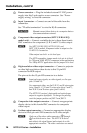
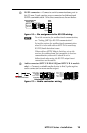
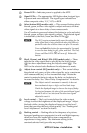
Power LED — Indicates power is applied to the MTP.
b
Signal LEDs — The appropriate LED lights when its signal type
is present and auto-detected. The signal types indicated are
either composite video, Y/C, YUV, or RGB.
c
Select button (SEQ models only) — This recessed button selects
the red, green, or blue video signal to adjust and resets all three
video signals to a skew delay of zero nanoseconds.
Use a Tweeker to press and release this button to cycle and select
the red, green, or blue video signal to adjust. The selected signal
is indicated by the Red, Green, and Blue LEDs (
d
).
N
The SEQ receiver automatically saves the setting for the
video signal that is being deselected when this button is
pushed or when the selection times out after 10 seconds.
Press and hold this button for approximately 3 seconds
to zero the skew delay for red, green, and blue. The Red,
Green, and Blue LEDS (
d
) all turn off. Release the
button.
d
R(ed), G(reen), and B(lue) LEDs (SEQ models only) — These
indicate the video signal that is selected by the Select button
(
c
) for skew adjustment using the Adjust control (
e
). The
LED for the selected color flashes as the adjustment is made.
e
Adjust skew control (SEQ models only) — This control delays
the selected red, green, or blue video signal by up to a maximum
of 62 nanoseconds (ns), in 2 ns incremental steps. Rotate the
control counterclockwise to reduce the delay or clockwise to
increase the delay. See “Skew Delay Compensation” for details.
N
The Adjust control’s movement is smooth; it does not
have mechanical steps or high- and low-limit stops.
Watch the displayed image to observe the steps of delay.
For best performance the skew of the most delayed signal
should be set to 0 ns (min) and the other two signals
adjusted to meet it.
f
Level control — The Level control alters the video output
voltage to affect the brightness of the displayed image. Adjust
the knob while viewing the displayed image to set the level/
boost that provides the best picture quality. See “Peaking and
Level Adjustment” section for details.
g
Peaking control — Peaking affects the sharpness of a picture.
Increased peaking can compensate for mid- and high-frequency
detail loss from low bandwidth system components or
capacitance in long cables. The minimum setting (at the
counterclockwise limit) provides no peaking.