


MTP U R Series • Introduction
5
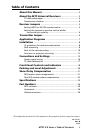
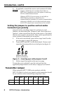
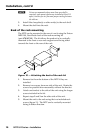
JMP1
JMP3
JMP2
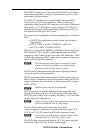
Default settings as
viewed from rear
N
The transmitter and receiver are designed for and
perform best with Extron Enhanced Skew-Free A/V cable
terminated in accordance with the TIA/EIA T 568 A
wiring standard. CAT 5 cables are acceptable but less
preferable. We also recommend the use of pre-terminated
and tested cables. Cables terminated on site should
be tested before use to ensure that they comply with
Category 5/5e/6 specifications.
The recommendations shown in the table apply for a
single transmitter and receiver. For example, the
maximum suggested range for 1024 x 768 video is 300’
(90 m) with Pre-Peak off and 600’ (150 m) with it on.
Receiver Jumpers
The MTP U R receivers have three jumpers on the main board.
Jumper 1 (JMP1) controls RS-232 directional communication,
and Jumpers 2 (JMP2) and 3 (JMP3) control vertical and
horizontal sync respectively.
By default, JMP1 is closed on all models and
configured to send serial data both ways
(bidirectional), transmitter-to-receiver and
receiver-to-transmitter. Jumpers 2 and 3 are
open (negative sync) by default.
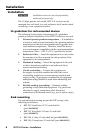
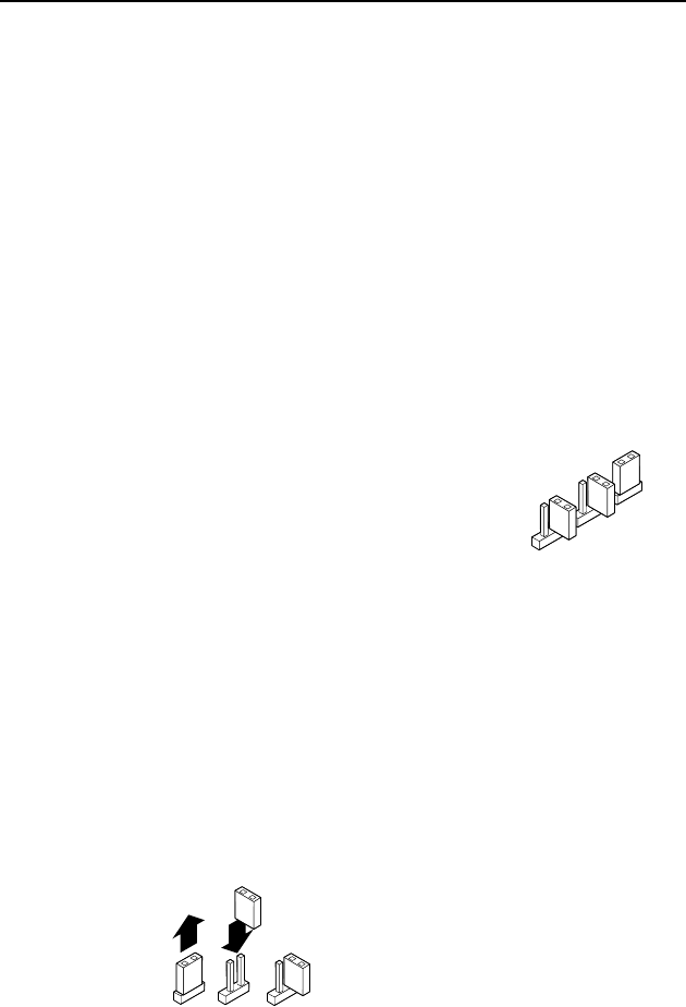
Setting JMP1 for RS-232 communication
Jumper 1 can be repositioned to enable unidirectional
communication as follows:
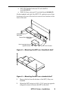
1. If applicable, disconnect all cables, remove the receiver
from its installation location, and remove any mounting
brackets installed.
2. Remove the two screws from either side of the receiver
(four screws total) and lift the top cover off of the receiver.
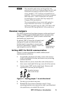
3. Locate jumper JMP1 on the main board. Remove and
reposition it over one pin (see figure 3).
Reposition the jumper
block to cover one pin.
Figure 3 — Setting jumper 1 to uni-directional
4. Put the top cover back into place.
5. Reinstall the four screws removed in step 2. If any
mounting brackets were removed in step 1, put them back
into position as you reinstall the screws