


MVX 44 / 48 / 84 / 88 VGA Matrix Switchers • Installation
2-2
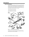
Installation
PRELIMINARY
Mounting the Switcher
N
Keep the switcher out of bright light to prevent interference with the IR signals
from the IR 501 remote control.
Tabletop use
For tabletop use, affix one of the supplied self-adhesive rubber feet to each corner of
the bottom of the switcher.
Rack mounting the switcher
All of the MVX Series VGA switcher models are housed in rack-mountable, 1U
high, full rack wide metal enclosures. The appropriate rack mounting kit is
included with each switcher. Rack mount the switcher as follows:
UL guidelines
The following Underwriters Laboratories (UL) guidelines pertain to the installation
of the MVX into a rack.
1. Elevated operating ambient temperature — If the equipment installed in a
closed or multi-unit rack assembly, the operating ambient temperature of the
rack environment may be greater than room ambient temperature. Therefore,
install the MVX in an environment compatible with the maximum ambient
temperature (Tma = +122 °F, +50 °C) specified by Extron.
2. Reduced air flow — Install the equipment in a rack so that the amount of air
flow required for safe operation of the equipment is not compromised.
3. Mechanical loading — Mount the equipment in the rack so that a hazardous
condition is not achieved due to uneven mechanical loading.
4. Circuit overloading — Connect the equipment to the supply circuit and
consider the effect that circuit overloading might have on overcurrent
protection and supply wiring. Appropriate consideration of equipment
nameplate ratings should be used when addressing this concern.
5. Reliable earthing (grounding) — Maintain reliable grounding of rack-
mounted equipment. Pay particular attention to supply connections other
than direct connections to the branch circuit (e.g. use of power strips).
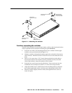
Mounting instructions
1. If feet were previously installed on the bottom of the switcher, remove them.
2. Attach the rack mount brackets to the switcher with the eight #8 machine
screws provided (figure 2-1).
3. Insert the switcher into the rack, aligning the holes in the mounting bracket
with those of the rack.
4. Secure the switcher to the rack using the supplied machine screws.