


2-3
MVX 44 / 48 / 84 / 88 VGA Matrix Switchers • Installation
PRELIMINARY
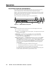
100-240V 0.3A
50-60Hz
MVX 88 V
GA A
RS-232
OUTPUTS
L
R
7
L
R
8
L
R
5
L
R
6
L
R
3
L
R
4
L
R
1
L
R
2
C
U S
LISTED
1
T
2
3
I.T
.E
.
1
2
3
4
INPUTS
5
6
7
8
1
2
OUTPUTS
3
4
5
6
7
8
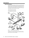
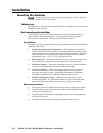
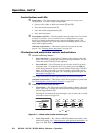
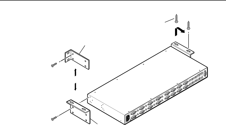
Rack-mount
Bracket (Included)
Table/
Wall-mount
Bracket (Optional)
Drill pilot holes
3/32” (2 mm) dia.,
1/4” (6 mm) deep.
#8 Screw (4 Plcs)
Each Side
Mounting Screws (2 Plcs)
Each Side
or
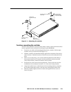
Figure 2-1 — Mounting the switcher
Furniture mounting the switcher
The MVX Series switchers can be mounted under a table or other horizontal surface
with an optional Extron under-desk mounting kit (part #70-222-01).
1. Secure the two table/wall mounting brackets to the switcher with the eight
machine screws provided in the kit (figure 2-1).
2. Hold the switcher with attached brackets against the underside of the desk or
other furniture. Mark the location of holes for screws on the underside of the
desk.
3. Drill 1/4” (6.4 mm) deep, 3/32" (2 mm) diameter pilot holes in the table or
desk at the marked screw locations from the underside/inside (concealed
side) of the furniture, where the switcher will be located.
4. Insert the four wood screws into the pilot holes. Fasten each screw into the
installation surface until just less than 1/4" of the screw head protrudes.
5. Align the installed screws with the slots in the mounting brackets, and place
the switcher against the surface, with the screws through the bracket slots.
6. Slide the switcher slightly forward or back, then tighten all four screws to
fasten it in place.