


QS-1
MVX 44 / 48 / 84 / 88 VGA Matrix Switchers • Quick Start
PRELIMINARY
Quick Start — MVX Series VGA Matrix Switchers
Installation
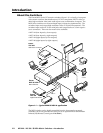
1 — Mount
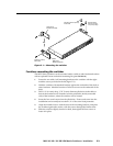
If desired, mount the switcher in a rack with the
supplied rack ears or mount the switcher under
a desk using an Extron MBU 149 1U enclosure
under-desk mount kit, part #70-222-01.
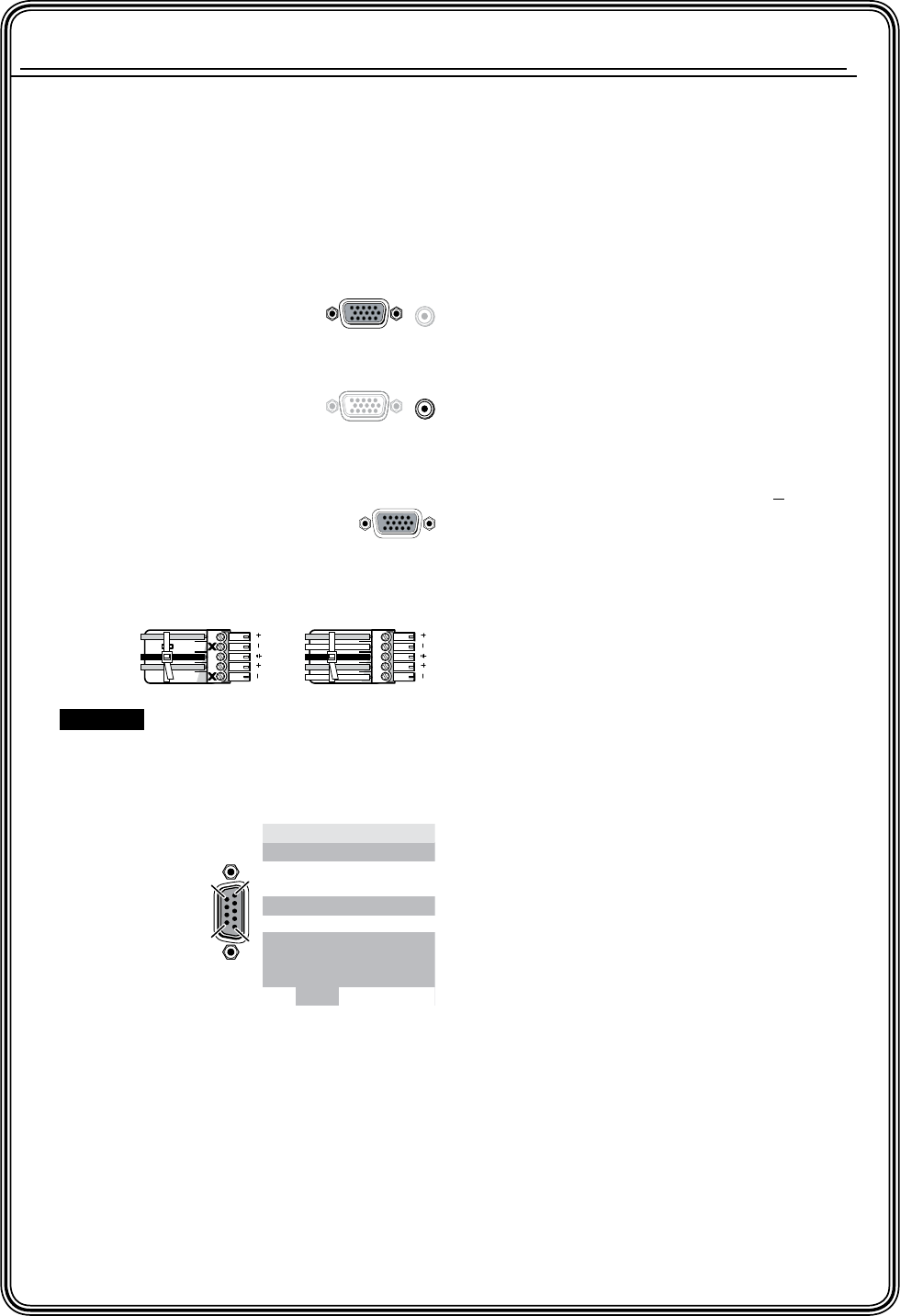
2 — Inputs
a Connect up to 4 or 8 high
resolution video inputs to
the 15-pin HD input connectors.
b
Connect up to 4 or 8 unbalanced stereo
audio
inputs to the
input 3.5 mm mini jack
connectors.
3 — Outputs
a Connect up to 4 or 8 high
resolution video devices to the
15-pin HD output connectors.
b Connect up to 4 or 8 balanced or
unbalanced stereo audio devices to the
output captive screw connectors.
4 — RS-232
If desired,
connect a control
system or a
computer to the
RS-232 port.
5 — Power
Connect the included IEC power cord into the
rear panel connector and plug the switcher in to a
100 VAC to 240 VAC, 50 or 60 Hz power source.
Definitions
Tie — An input-to-output connection
Set of ties — An input tied to two or more
outputs
Configuration — One or more ties or sets of ties
Current configuration — The currently active
configuration (also called configuration 0)
Preset — A configuration that has been stored.
One preset can be assigned to each input and
output button. 16 presets are available via
RS-232 control. When a preset is retrieved
from memory, it becomes the current
configuration.
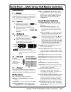
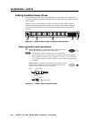
Front Panel Features
Power/data/audio LED — Indicates power is
applied. This LED also has two secondary
functions:
Serial communication function — The
Power/data/audio LED blinks off and
on to indicate that an IR signal has been
received.
Audio level function — In Audio Setup mode,
the Power/data/audio LED lights when
the selected input audio signal is > the
reference level and is unlit when the signal
is below the reference level. Adjust the
gain until the LED blinks frequently. If the
LED is almost always on, but occasionally
blinks off, the level is too high. If the LED
is almost always off, but occasionally
blinks on occasionally, the level is too low.
I/O button selects video and audio, video, or
audio for input selection.
Video and Audio LEDs indicate whether video
and audio, video, or audio is selected. The
Audio LED blinks to indicate audio is broken
away.
Input buttons select an input to tie to an output.
Input LEDs identify the input selected for the tie.
Output buttons select output(s) to tie to an input.
Output LEDs identify output(s) selected for the
tie.
Enter button saves configuration changes.
Preset button selects Save Preset mode or Recall
Preset mode, in which a configuration can be
saved as a preset or recalled.
Audio Setup button and LED enable you to
view and/or change the current audio
level setting for each input. Audio Setup is a
secondary function of the I/O button.
Down (
<
) and Up (
>
) buttons and LEDs decrease
or increase the audio level for the selected
input and indicate the decrease and increase.
On 8-output switchers,
<
and
>
are secondary
functions of the Output 7 and Output 8 buttons.
+dB/–dB LEDs indicate the polarity of the audio
level setting (+dB = gain, –dB = attenuation).
+dB and –dB are secondary functions of the Video
and Audio LEDs.
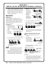
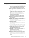
CAUTION Connect the sleeve to ground.
Connecting the sleeve to a negative (-)
terminal will damage the audio output
circuits.
Unbalanced Output
Balanced Output
L R
Ring
Tip
Sleeve(s)
Tip
Ring
Sleeve(s)
Tip
Tip
NO GROUND HERE.
NO GROUND HERE.
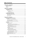
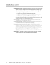
1
1
1
5
6
9
Pin RS-232 Function
1—N/C
2TXTransmit data
3RX Receive data
4—N/C
5 Gnd Signal ground
6—N/C
N/C
N/C
7—
8—
—
Hardwired IR9