


Operation, cont’d
MVX 44 / 48 / 84 / 88 VGA Matrix Switchers • Operation
3-4
PRELIMINARY
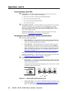
Control buttons and LEDs
e
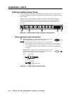
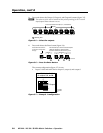
Enter button — The Enter button saves changes when you set up a new
configuration. To create a simple configuration:
• Specifyvideo,audio,orboth(seecontrols[g]and[h]).
• Pressthedesiredinputbutton(c).
• Pressthedesiredoutputbutton(s)(d).
• PresstheEnterbutton.
f
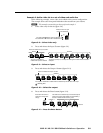
Preset button and LED — The Preset button activates either Save Preset mode
or Recall Preset mode. Save Preset mode saves a configuration as a preset.
Recall Preset mode recalls and activates a previously-defined preset. The
Preset button indicates Save Preset mode when it is blinking and Recall Preset
mode when it lights steadily.
Alternate reset function — This button is also used to clear all ties and
presets. See “Clearing all ties and presets” on page 3-24.
I/O selection and audio/video controls and indicators
g
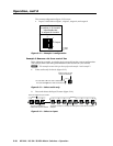
I/O and Audio Setup button —
• Press and release — Pressing the I/O button cycles through video and
audio, video only, or audio only for input and output selection. See the
Video and Audio LEDs (
h) for the sequence.
• Press and hold — The I/O button also serves as the Audio Setup mode
selection button. To enable the Audio Setup mode, press and hold the
Audio Setup button for about 2 seconds until the Audio Setup LED (
i)
lights. In Audio Setup mode, you can view and/or change the current
audio level setting for each input. See “Adjusting input audio gain and
attenuation” on page 3-18.
Audio Setup mode times out after approximately 30 seconds of inactivity.
Alternate reset function — This button is also used to perform a system reset.
See “Resetting the system to factory defaults” on page 3-25.
h
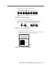
Video/+dB LED and Audio/–dB LED —
• I/O selection — The Video and Audio LEDs indicate whether video and
audio, video only, or audio only will be selected using the input buttons
(
c) and output buttons (d).
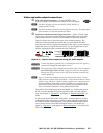
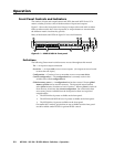
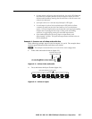
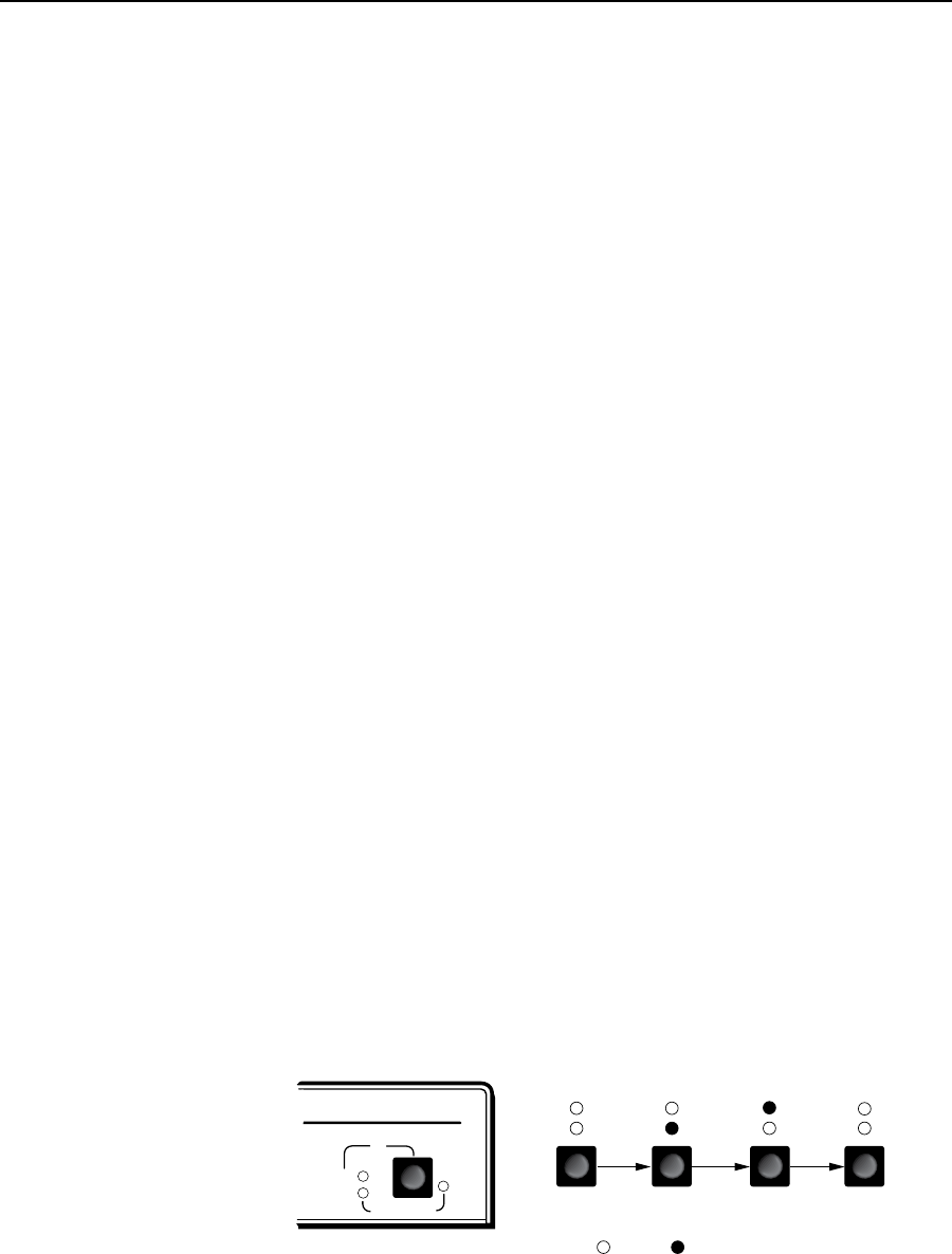
Pressing the I/O button advances through a cycle of video and/or audio
selections as shown on figure 3-2.
MVX SERIES
VGA/AUDIO MATRIX SWITCHER
I/O
AUD
AUDIO SETUP
Default
= ON = OFF
VID
+dB
-dB
AUD
VID
+dB
-dB
Video Only
AUD
VID
+dB
-dB
Audio Only
AUD
VID
+dB
-dB
Video & Audio
AUD
VID
+dB
-dB
PressPressPress
Figure 3-2 — Video and/or audio selection cycle
• Audio Setup mode — The –dB and +dB LEDs indicate the polarity of the
audio level setting. See “Adjusting input audio gain and attenuation” on
page 3-18. Both LEDs light to indicate unity gain (0 dB).