


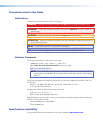
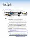
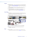

Outputs
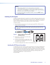
f HDMI video output — Connect a suitable display device to this female HDMI digital
video output connector. Use the Extron LockIt device to secure the HDMI cable at
the switcher. See “Securing the HDMI cable” on page 7 for method of securing the
cable.
g Line out audio output — Connect an external amplifier, recording, podcasting, or
assisted listening device to this 3.5 mm captive screw 5‑pole connector.
h Amplified audio output — Connect speakers to this 5 mm captive screw 4‑pole
connector. The amplified audio output is capable of outputting 50 watts
(2 x 25 watts rms) for 4 and 8 ohm speakers. See Connector Wiring for wiring
details.
Control Ports
i IR insert port — For IR control for a source device, connect the IR Out port on the
MLC to this 3.5 mm captive screw 2‑pole connector. This routes IR transport control
signals via an IR device connected to the PVT wallplate front panel.
j Remote control port — Connect a host computer, control system, or MLC controller
to this 3.5mm captive screw 3‑pole connector for direct switcher control via RS‑232.
2
3
GROUND
1
IR IN
GROUND
IR OUT
CM
SCP
GROUND
GROUND
Tx
Rx
DISPLAY
RS-232/IR
LAN
PRESS TAB WITH
TWEEKER TO REMOVE
A B
MLS PWR
RS-232 12V
DIGITAL
I/O
A B C D E
COMM LINK
+V OUT
GROUND
Tx
Rx
+12V IN
CONFIG
DISPLAY
VOLUME
MLC 104 IP PLUS
ON
VCR
DVD
PC
OFF
1
2
3
4
RS-232
LR
DO NOT
GROUND
OR SHORT
SPEAKER
OUTPUTS
4/8
Ω
3A MAX
POWER
12V
HDMI
1/2
SIGLINKSIG LINK
3/4
INPUTS OUTPUT AUDIO OUT AMPLIFIED AUDIO OUT
PAGING
SENSOR
PVT IN PVT IN
L
R
AUX OVER PVT REMOTE
VOICELIFT
LAN 1 LAN 2 LAN 3
INPUT 5
+V
L
R
RS-232
Tx Rx
IR
SG G
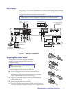
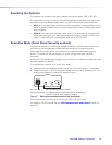
MLC 104 IP Plus right side panel
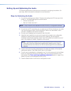
MLS and Power ports
RS-232 12V
MLS PWR
AB
Rx
Tx
GROUND
GROUND
+12V IN
To Supplied PVS
Power Supply
(12 VDC, 1 A max.)
NOTES:
• You must connect a ground wire
between the MLC and PVS.
• If you use cable that has a drain
wire, tie the drain wire to ground at
both ends.
G
Ground
+12 VDC input
Ground (Gnd)
Transmit (Tx)
B
Receive (Rx)
A
Transmit (Tx)
Receive (Rx)
Tx
Rx
IR control
S
Ground
G
IR Out
Rx
Tx
Projector
GROUND
IR OUT
Tx
Rx
DISPLAY
RS-232/IR
Ground
RS-232
PVS 405D
CLASS 2 WIRING
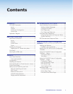
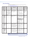
Figure 3. MLC 104 IP Plus RS-232 and IR Connections to the PVS 405D
k LAN ports — Connect to these three RJ‑45s that act as a built‑in 3‑port
10/100Base‑T network switch.
Power
l Power receptacle — Connect to the supplied 12 VDC 4 A power supply to this
orange female 2‑pole captive screw connector. See page 47 for the wiring diagram.
PVS 405D Switcher • Introduction 5