


PVS 405D • Connector Wiring 50
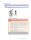
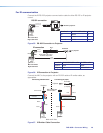
NOTE: Some projectors require NULL connection wiring, which inverts the Tx and Rx
connections. See the projector guide for details.
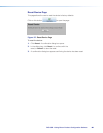
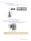
IR control for a connected input device such as a BluRay player can be made through the
PVT wallplate.
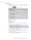
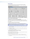
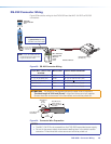
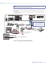
The connections between the MLC 104 IP Plus and the PVS 405D switcher should look
like the figure below.
LR
DO NOT
GROUND
OR SHORT
SPEAKER
OUTPUTS
4/8
Ω
3A MAX
POWER
12V
HDMI
1/2
SIG LINK SIG LINK
3/4
INPUTS OUTPUT AUDIO OUT
PVS 405SA IP
AMPLIFIED AUDIO OUT
PAGING
SENSOR
PVT IN PVT IN
L
R
AUX OVER PVT REMOTE
VOICELIFT
LAN 1 LAN 2 LAN 3
INPUT 5
+V
L
R
RS-232
Tx Rx
IR
SG G
2
3
GROUND
1
IR IN
GROUND
IR OUT
CM
SCP
GROUND
GROUND
Tx
Rx
DISPLAY
RS-232/IR
LAN
PRESS TAB WITH
TWEEKER TO REMOVE
A B
MLS PWR
RS-232 12V
DIGITAL
I/O
A B C D E
COMM LINK
+V OUT
GROUND
Tx
Rx
+12V IN
CONFIG
DISPLAY
VOLUME
MLC 104 IP PLUS
ON
VCR
DVD
PC
OFF
1
2
3
4
RS-232
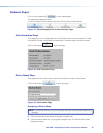
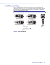
MLC 104 IP Plus right side panel
MLS and Power ports
RS-232 12V
MLS PWR
AB
Rx
Tx
GROUND
GROUND
+12V IN
NOTES:
• You must connect a ground wire
between the MLC and PVS.
• If you use cable that has a drain
wire, tie the drain wire to ground at
both ends.
G
Ground
+12 VDC input
Ground (Gnd)
Transmit (Tx)
B
Receive (Rx)
A
Transmit (Tx)
Receive (Rx)
Tx
Rx
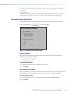
IR control
S
Ground
G
IR Out
Rx
Tx
Projector
GROUND
IR OUT
Tx
Rx
DISPLAY
RS-232/IR
Ground
RS-232
To Supplied
PVS Switcher
Power Supply
(12 VDC, 4 A)
To Blu-ray (or similar) input device
Optional PVT Front Panel
IR Output Connection
VGA IN
AUDIO
IN OUT
LOCAL OUT
AUDIO IN
HDMI IN
IR OUT
S
G
HDMI IN #1
RGB IN #2
IR Emitter
STP Input Cable
CLASS 2 WIRING
Figure 38. MLC wiring to the PVS 405D Switcher