


Gain Control
Individual channel input sensitivity control
Individual channel input gain control adjustments are made by rotating the adjustment
encoder for the selected input button. The adjustment range is ‑18 dB to +24 dB, with the
default set at 0 dB.
NOTE: Adjusting input sensitivity for all inputs ensures that all inputs are at the same
level and at the highest level possible before clipping occurs.
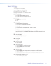
Front panel input sensitivity adjustment
To make sure the right input sensitivity is attained, do the following:
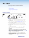
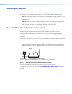
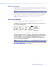
For the active input (with the LED lit), rotate the level adjustment encoder until the Normal
LED is lit and the Peak LED only lights occasionally.
NOTE: Having the audio level beyond the point at which the peak LED flashes results
in a distorted output signal (clipping).
PEAK
NORMAL
SIGNAL
AUDIO LEVEL ADJUST
PAGING
SENSOR
SENSITIVITY
VOICELIFT
PEAK
NORMAL
SIGNAL
INPUT
PEAK
NORMAL
SIGNAL
Signal threshold;
raise input gain.
Level has been
properly adjusted.
Level set too high,
lower input gain.
Figure 8. Front panel Input audio Min/Max LED and adjustment encoders
Individual gain adjustment can also be made by configuration software or SIS commands
(see “SIS Communication and Control” for details on SIS commands).
Repeat the steps for the other inputs as desired.
NOTE: The Peak/Normal/Signal LEDs function as the Aux Input level indicator only
when the switcher is in the “AUX Adjust” mode.
PVS 405D Switcher • Operation 13