


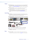
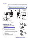
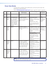

Final Setup
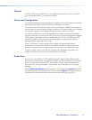
With an MLC 104 IP Plus as a standard MLC controller in the PoleVault system package,
the PVS 405D switcher completed setup should look similar to the figure below.
Ensure all connections are correctly made and secure.
NOTE: See the PoleVault System Installation Guide and MLC 104 Plus Series
Setup Guide for full MLC installation, configuration, and operating details.
LR
DO NOT
GROUND
OR SHORT
SPEAKER
OUTPUTS
4/8
Ω
3A MAX
POWER
12V
HDMI
1/2
SIG LINKSIG LINK
3/4
INPUTS OUTPUT AUDIO OUT
PVS 405D
AMPLIFIED AUDIO OUT
PAGING
SENSOR
PVT IN PVT IN
L
R
AUX OVER PVT REMOTE
VOICELIFT
LAN 1 LAN 2 LAN 3
INPUT 5
+V
L
R
RS-232
Tx Rx
IR
SG G
HDMI Output
to Display Device
HDMI
Connector
Aux Audio
Input 5
Audio Output to Speakers
Red Positive (+)
Black Negative (-)
Speaker
wire color
PVS terminal
(left and right)
Line Out
Output (Audio)
Paging
Sensor
Aux
Input
Supplied PVS Switcher
External Power Supply
(12 VDC, 4 A max.)
3-port 10/100 Ethernet Switch
Connect to ports as follows:
1. TCP/IP network
2. MLC controller
3. Optional network device
5
7
12
Power Connector
HDMI/RGB
PVT SW HDMI RGB D
HDMI or RGB video/audio, Inputs1/2 and 3/4
1 STP cable with RJ-45 connectors
VGA IN
AUDIO
IN OUT
LOCAL OUT
AUDIO IN
HDMI IN
IR OUT
S
G
6 2 3
VoiceLift
Receiver
4
IR control
10
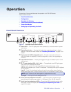
MLC 104 IP Plus
RS-232 input
White Tx on RS-232 port
Violet Rx on RS-232 port
Drain wire Ground (G)
Black Power Supply (–)
Red Power Supply (+)
MLC
wire color
To PVS terminal
9
11
8
+V
SG
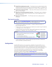
MLC 104 IP Plus right side
panel MLS and Power ports
RS-232 12V
MLS PWR
AB
Rx
Tx
GROUND
GROUND
+12V IN
B
Ground
+12 VDC input
To Supplied
PVS Switcher
Power Supply
(12 VDC, 4 A max.)
NOTE: If you use cable that has
a drain wire, tie the drain wire
to ground at both ends.
NOTE: You must connect
a ground wire between
the MLC and PVS.
Ground (Gnd)
Transmit (Tx)
B
Receive (Rx)
A
Transmit (Tx)
Receive (Rx)
B
A
1
G
Figure 5. PVS 405D Connections
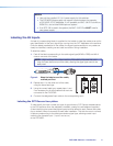
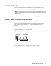
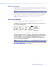
Securing the HDMI cable
The supplied Extron LockIt lacing bracket makes it
possible to secure a standard HDMI cable to the
PVS 405D switcher.
NOTE: The tie wrap can also be tightened using
pliers or similar tools.
To securely fasten an HDMI cable to the PVS 405D:
a. Plug the HDMI cable into the rear panel HDMI connector.
b. Loosen the HDMI connection mounting screw from the rear
panel enough to allow the LockIt lacing bracket to be placed
over it. The screw does not have to be removed.
c. Place the LockIt lacing bracket on the screw and against the
HDMI cable connector.
d. Tighten the screw to secure the bracket.
e. Place the included tie wrap around the HDMI connector and the
LockIt lacing bracket and tighten as shown in the images at right.
c
OUTPUT
a
b
e
3
d
3
LLLLLLL
PVS 405D Switcher • Rear Panel Connections 7